hello
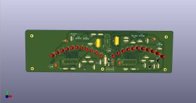
I am rebuilding my 750C into a 750B.
I have rebuilt the vu meter in kicad but am a little confused about
the hock up of the LM324 ?
from what I can understand it is the LM324 ic pin 4 to +15V and pin 11 between R527 and D507 ?
would be really happy if some one can confirm i am on the right way.
I am rebuilding my 750C into a 750B.
I have rebuilt the vu meter in kicad but am a little confused about
the hock up of the LM324 ?
from what I can understand it is the LM324 ic pin 4 to +15V and pin 11 between R527 and D507 ?
would be really happy if some one can confirm i am on the right way.
Attachments
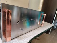

Hi BB, Nice work, looks great! Love the copper handles
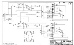
Yes, the -Ve rail for the meters is derived from the amplifier -Ve rail as there's no separate low voltage negative supply
And as Duke has pointed out, the voltages of the 750 are higher requiring a higher value 5.1k 2W resistor for R527 to drop more volts
Also, suggest raising R527 from the PCB by 1-2mm, if you have space under the front panel, to avoid scorching the PCB in the longer term due to heat from the resistor
Cheers, Ralph
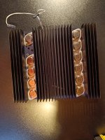
Tnx Ralphs always nice with good locking handles.
So the ic will have -10V on the negative side and +15 on the positive?
Tnx for the advice, it will be space to rice the resistor the led's is going to sit on the other side of the pcb later. there was not possible to do that on the 3D picture.
Maby it will be a 3W Resistor then its quite a big drop from -75V
Sounds good to me. The different +/- supplies for the opamps are no issue
I'm sure some of the BGW experts can confirm
I'm sure some of the BGW experts can confirm
Hi ralphs99
We never had a problem with the heat on the display. I guess you might see my name on the schematic?
Duke Aguiar 8 years @ BGW
We never had a problem with the heat on the display. I guess you might see my name on the schematic?
Duke Aguiar 8 years @ BGW
its cool to talk with somebody how really knows tanks again Ralph an Duke !
I will update this tread with some pictures when i received the VU pcb.
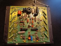
Have switched to mjl15024/25 do i aim for same bias as usual?
I will update this tread with some pictures when i received the VU pcb.
Have switched to mjl15024/25 do i aim for same bias as usual?
Attachments
Outside of my expertise. I'll defer to those people that have tried substituting transistors
You will want to check the amplifier is stable with the new output transistors. You may need to adjust compensation? #Duke?
In general, as I understand it, bias affects stable thermal operation and crossover distortion. So I think I would start with the same bias current with the amplifier cold, and check distortion at a low power output level and medium to high frequency, varying the bias slightly to see if there's a point at which distortion changes markedly. Then heat the heatsinks slowly with a heatgun (or run amp hard if you have a suitable dummy load) to check bias isn't changing too much as heatsink temperature rises
Happy to hear about other people's experience with output stage transistor substitution?
Cheers, Ralph
- Home
- Amplifiers
- Solid State
- converting BGW 750C to BGW 750B VU meter PSU hock up