Converting a B&K Receiver to a Power Amp
I’m trying to convert my B&K AVR 307 receiver to a seven channel power amp. You may ask, why would I want to do this? Well, the AVR 307 was a top receiver five years ago. However, in the fast-moving world of new formats and connections, the AVR 307 is obsolete. However, its amp section is still first-rate (150w/channel x 7.)
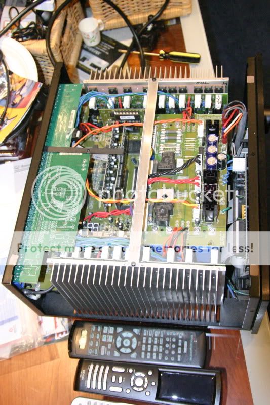
One can see from the picture below how massive the amp section is:
My theory is that by finding the place where the pre-amp board connects to the amp, I can separate that connection and install RCA inputs to feed the amp directly.
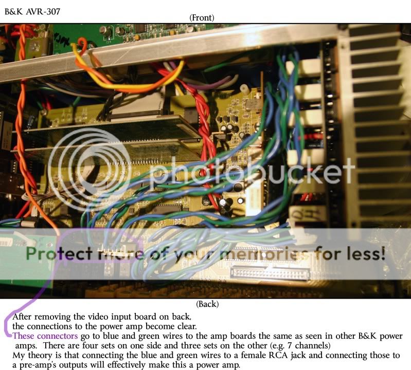
 Note the markings, such as "RF" (Right Front), "LF" (Left Front), "CF" (Center Front), etc.
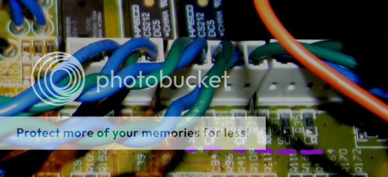
Not ever doing a project like this, I don’t know whether the green or blue wire goes to the center of an RCA connector or the outside. I also want to use similar modular connectors – in case I ever wanted to return this to a receiver. However, I have no idea where to get those type of connectors. I already purchased the same blue and green wire that B&K uses (Brand=Spectrum.)
Any guidance is appreciated.
I’m trying to convert my B&K AVR 307 receiver to a seven channel power amp. You may ask, why would I want to do this? Well, the AVR 307 was a top receiver five years ago. However, in the fast-moving world of new formats and connections, the AVR 307 is obsolete. However, its amp section is still first-rate (150w/channel x 7.)
One can see from the picture below how massive the amp section is:
My theory is that by finding the place where the pre-amp board connects to the amp, I can separate that connection and install RCA inputs to feed the amp directly.
Not ever doing a project like this, I don’t know whether the green or blue wire goes to the center of an RCA connector or the outside. I also want to use similar modular connectors – in case I ever wanted to return this to a receiver. However, I have no idea where to get those type of connectors. I already purchased the same blue and green wire that B&K uses (Brand=Spectrum.)
Any guidance is appreciated.
Anyone know where I can get matching male connectors, as shown in the last photo? They are 5-pin. I think they are called Molex connectors, as per the schematic that I have.
I find that hard to believe since different blue/green wires, from the amp boards (on the sides,) lead to the speaker terminals.ostripper said:Those blue/greens are the amps outputs, not the inputs.
OS
But I'll double check to confirm.
After having seen my thread, you know that I am trying to get it running without the preamp section attached at all. This will be very helpful though that your unit is in perfect working order. Do you have a multimeter to test some voltages for me?
Another member, Iain Mcneill, posted on my thread and is trying to help me sort things out. I don't have time to post the full details at the moment, but if you want to also get the amp running without the preamp, these tests may benefit both of us. Basically we want to compare the voltage in the orange "CTRL" lead in various states to see what effect it has on the operation of the amp modules. I'll be posting more later tonight. If you want to, you can read what he has posted more recently on my thread to get an idea of what I'm talking about.
Another member, Iain Mcneill, posted on my thread and is trying to help me sort things out. I don't have time to post the full details at the moment, but if you want to also get the amp running without the preamp, these tests may benefit both of us. Basically we want to compare the voltage in the orange "CTRL" lead in various states to see what effect it has on the operation of the amp modules. I'll be posting more later tonight. If you want to, you can read what he has posted more recently on my thread to get an idea of what I'm talking about.
Hello again MTA,
For staters, we need to see if the voltage on the "CTRL" lead changes depending on if the amp is activated or not. Lets go about this very carefully...
Take a look at the power supply board. On the left side (looking from the front) there are groups of three wires leading from the power supply board to the amp modules. 3 wires per amp module. A red wire (V+), a black wire (V-), and an orange wire (CTRL).
~~~~~~~~~~~~~~~~~~~~~~~~~~
*For each measurement:
-Set your multimeter to Volts DC, the the next step above 65V (mine is 200V).
-take the black lead and place it on a ground terminal, labelled "GND" (there should be a green wire coming from it).
-place the red lead on the terminal of one of these orange wires on the power supply board.
-read it 🙂
~~~~~~~~~~~~~~~~~~~~~~~~~~~~~~~~~
*Take the above measurements when:
-the amp is in sleep/standby
-the amp is powered on (with no music playing)
-the amp is powered on (with music playing)
-any other unique power settings you can think of
Record voltage measurements for each of these and let me know what you get. I have no way to test this, as my receiver no longer operates normally. Hopefully the change in voltage of the CTRL wires will tell us something about their usage.
Thread ressurrect!!
I'm tinkering about with this mod on my AVR307. It had a bad video board or something - the dreaded drop-out issue...
So I gutted it today, and marked all the amp inputs, clipped them from the board and pulled everything except the power board, amp board and the front panel items.
I ran the front L and front R to some RCA's I scavenged from one of the boards..
No output.
Now - I've only skimmed the thread... but I'm assuming there is a signal that is passed to turn the amps on via a relay somewhere...
So - Next, in a day or two, I'll pull the power board and see what is in there and if there is a "sense" on the amp boards.
I'm going to give it a few days to hopefully let the power caps discharge - definitely dont want to get zapped.
Last edited:
Yes, can we please revive this thread? My AVR307 just ate it last month and I would like to know if anyone was successful in converting it into a stand-alone amp.
I have a B&K Reference 200.7 which is simply A big 200 watt per channel 7 channel mosfet power amp (and space heater...LOL) with XLR and RCA inputs. The amp boards in this receiver look Identical to the ones in my Reference. I have the schematics for my amp if it will. help. So if they are the same boards I do not see why it cannot be converted to just a stand alone power amp. I think the main difference between my amp and the receivers are that with the reference 200.5 and 200.7 series the receiver was a separate stand alone component and the amp was just that, an amp.
Its interesting that this is mentioned as my amp has worked for many years but the preamp /receiver unit quit like 2 years ago. Go figure...
Its interesting that this is mentioned as my amp has worked for many years but the preamp /receiver unit quit like 2 years ago. Go figure...
On my BK amp.. the inputs are directly connected to rca input.. so I cant see why it would work to connect the blue and green directly to an input (with a volume control of course).. However, doesnt the amp have a direct setting for input already? Like a 5/7 channel direct.
get some shielded cable, pull out a resistor or jumper from 7.1 input and connect each input directly to each amplifier input.
You will need an external 7 channel preamp.
You will need an external 7 channel preamp.
As an owner of a BK 5000, I knoticed all BK amps are very similar in build and are seperate from other components. That being said.. I kind of figured it would be an easy peasy connection from RCA input directly to amp. I would tie the back RCA input jacks (that are already installed in back of BK) directly to amp and just plug in preamp from there.
What I did was use some tyco connector to the green and blue conncetors and solder to the component video rca connector. But if anyone try this make sure you ground the rca connector to ground of the receiver or you will damage your speakers. Once I did this I started unhooking the different connectors to the preamp until I got to the AON (connector 1) on the power supply and tied it the control on the amp section (the orange wire). Know I only have the power supply and the amp left in the receiver glutted the rest of the stuff.
You have my admiration, Mr. Graham!What I did was use some tyco connector to the green and blue conncetors and solder to the component video rca connector. But if anyone try this make sure you ground the rca connector to ground of the receiver or you will damage your speakers. Once I did this I started unhooking the different connectors to the preamp until I got to the AON (connector 1) on the power supply and tied it the control on the amp section (the orange wire). Know I only have the power supply and the amp left in the receiver glutted the rest of the stuff.
Do you have any pictures of the final work?
- Status
- Not open for further replies.
- Home
- Amplifiers
- Solid State
- Converting a B&K Receiver to a Power Amp