I have a Jamo S810 sub which only has a mono line level input and a stereo amplifier that outputs 100W RMS at 8ohms per channel without a sub out. It has a line out but that is not volume controlled. I looked into off the shelf LOCs, but they are at most rated at 40W per channel and then I still would need to down mix to mono. Plus most of the LOCs use isolation transformers, which from my research don't function well at low frequencies (at least not ones that are less than $60).
So I started looking up schematics of subs with speaker level inputs to see how pros do it. And low and behold they use simple voltage deviders mostly followed by a summing amplifier. I even looked at an amplifier (Yamaha R-N602) with sub output and it too just takes speaker level outputs, attenutes them and sums them up using summing amplifier.
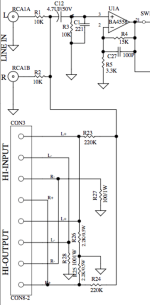
However I was able to find examples of subs (Polk PSW10 and PSW202) that don't even use an op amp before combining the signal with line input (attached). So I "isolated" what seemed the inportant parts of the circuit an pared it down to the second attached image. I threw it all together, using 4 27 ohm 1/4W resistors in series instead of the 100 ohm 1W as I did not have those available. And it seems to work. I say seems because I have no way to measure distorsion or any possible negative effects to the sound quality. All I can tell is that the sub produces sound, there is no hum and the amp has not blown up nor is complayining.
I wanted to post it here to get a second opnion on why this might or might not be a good idea, or if I missed something inportant from the original circuit. What is the function of the 100 and 2K2 resistors? Why would they possibly use 220K and 10k for the summing/voltage devider? What is the C1 221 (which I omitted) in the original schematic for?
Then perhaps this could be helpful as a resource for anybody that might be searching for a thing like this in the future.
Note: Despite throwing around terms like "summing amplifier", "simple voltage devider", "isolation transformer", I am not going to pretend I have more than a rudimentary understanding of electronic circuicts. I've learned most of those from my research about this. So wait until others with more experience weigh in.
Anyway, any pointers and constructive criticism are much appreciated.
So I started looking up schematics of subs with speaker level inputs to see how pros do it. And low and behold they use simple voltage deviders mostly followed by a summing amplifier. I even looked at an amplifier (Yamaha R-N602) with sub output and it too just takes speaker level outputs, attenutes them and sums them up using summing amplifier.
However I was able to find examples of subs (Polk PSW10 and PSW202) that don't even use an op amp before combining the signal with line input (attached). So I "isolated" what seemed the inportant parts of the circuit an pared it down to the second attached image. I threw it all together, using 4 27 ohm 1/4W resistors in series instead of the 100 ohm 1W as I did not have those available. And it seems to work. I say seems because I have no way to measure distorsion or any possible negative effects to the sound quality. All I can tell is that the sub produces sound, there is no hum and the amp has not blown up nor is complayining.
I wanted to post it here to get a second opnion on why this might or might not be a good idea, or if I missed something inportant from the original circuit. What is the function of the 100 and 2K2 resistors? Why would they possibly use 220K and 10k for the summing/voltage devider? What is the C1 221 (which I omitted) in the original schematic for?
Then perhaps this could be helpful as a resource for anybody that might be searching for a thing like this in the future.
Note: Despite throwing around terms like "summing amplifier", "simple voltage devider", "isolation transformer", I am not going to pretend I have more than a rudimentary understanding of electronic circuicts. I've learned most of those from my research about this. So wait until others with more experience weigh in.
Anyway, any pointers and constructive criticism are much appreciated.
Attachments


That circuit assumes the amp outputs are single-ended, ie not bridge-tied (most class D amps are bridge-tied, note).
If you must have isolation you will need transformers and audio transformers are expansive.
But power transformers are less expansive, for full frequency and low distortion I would not use them.
But in your application it could work, here is an example:
Marque : JAMECO RELIAPRO
4,3 4,3 sur 5 étoiles 74 évaluations
Choixd'Amazonpour « ac to ac wall adapter »
I will post the circuit soon .........
But power transformers are less expansive, for full frequency and low distortion I would not use them.
But in your application it could work, here is an example:
Jameco Reliapro ADU090150A2231 Adaptateur mural AC vers AC 9 V @ 1500 mA Droit Prise femelle 2,5 mm Noir
Marque : JAMECO RELIAPRO
4,3 4,3 sur 5 étoiles 74 évaluations
Choixd'Amazonpour « ac to ac wall adapter »
I will post the circuit soon .........
That is interesting.
Why is there a 1K resistor between Tr1 and Tr2?
Also as I was researching this, one reason stated for why the audio isolation transformers were so expensive was that they had to have relatively high winding counts, requiring very thin gauge wire, and some not standard core materials. My understanding was that otherwise there would be distortion at low frequencies. Does this problem diminish with bigger transformers as you recommend?
Thirdly, is there any problem with the circuit in my second attachment?
I found this diyaudio reply in a thread about using power transformer in audio setup
https://www.diyaudio.com/community/...mer-as-output-transformer.188271/post-2561092
So it doesn’t seem to be ideal although they state that it “may not be audible”. Probably the -3dB around 55Hz might be a bigger issue.
https://www.diyaudio.com/community/...mer-as-output-transformer.188271/post-2561092
- Core saturation tends to become a significant problem below 50Hz. This is visible on a scope and tends to look pretty bad, but may not be audible. Don't expect much output power below 35Hz.
On the low end, the -3dB point is somewhere around 55Hz if memory serves.
So it doesn’t seem to be ideal although they state that it “may not be audible”. Probably the -3dB around 55Hz might be a bigger issue.
The 1 K resistor is to '' calibrate attenuation '' so if output levet is too low you may remove it.
transformer have a ratio 13:1 and with both resistor attenuation is around 26:1 if potentiometer is set for maximum output.
The transformer is made to work at 120 volts at 60Hz so th core is selected for these parameters.
But saturation voltage is proportional to frequency so 120V 60Hz will use same magnetic level as 60V 30Hz or 40V 20 Hz or 30V 15 Hz. and so on.
I dont expect saturation problem in your application.
- Home
- Source & Line
- Analog Line Level
- Convert speaker level stereo to line level mono for sub