I am building Pete Millet's DCPP "Engineer's Amp". I am not using the stock PT specified in the schematic.
Rather than a PT with a 50V winding with a center tap (50-0-5), I have a transformer with a 130V winding (no center tap) (130-0).
I want to convert the stock bias supply (see attached) to be used with my 130V (no center tap) transformer.
I was thinking since no CT on my transformer I would just use a bridge recto. Then a 100V zener diode to bring the voltage down.
Stock bias supply puts out (1.414 x 50V ~= 70V) where the new winding would put out (1.414 x 130V ~= 180V). So I figure I have to drop at least 100V and the easiest way to do with would be with a zener. Thoughts?
Side note: what current does the bias supply itself actually use?
Attachments
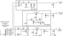
The "C-" load is relatively constant: 17mA of LTP cathode CCS + about 3mA bias part (per channel).
If the input DC voltage is -for example- 180V vs. 70V (110V difference), and load is 20mA,
try to increase R12 from 100R to
110V/0.02A= 5500R.
You can use R12= 2k and R12a (between C8-C16) = 2k5.
The correct calculation of R12+R12a is (at 20ma load!):
Rresult = (DC voltage of C1 - 60V)/20mA
If you stabilized the bias voltage and B+ not stabilized (only smoothed), the AC line fluctuation will causes bias point fluctuation too.
Both or neither must be stabilized/not stabilized.
Last edited:

Sorry what do you mean when you say,
The B+ and screen supplies are regulated, the bias supply is not regulated.
DCPP "Engineer's Amp". schematic
The bias supply (C-) is supply the output tubes fixed bias supply. The other tube's have cathode biasing with CCS loads. So I am confused how the non power tubes come in to this.The "C-" load is relatively constant: 17mA of LTP cathode CCS + about 3mA bias part (per channel).
I understand line flucuations but I am confused at what you mean.If you stabilized the bias voltage and B+ not stabilized (only smoothed), the AC line fluctuation will causes bias point fluctuation too.
Both or neither must be stabilized/not stabilized.
The B+ and screen supplies are regulated, the bias supply is not regulated.
DCPP "Engineer's Amp". schematic
See the attachment.

The "C-" is the negative supply of the LTP (17mA CCS) and the bias part.
---------------------
http://www.pmillett.com/DCPP.htm
Pete wrote:
"
The power supply
The power supply uses silicon rectifiers and a MOSFET ripple filter for the B+ - no expensive and heavy chokes here. The screen voltage of ~150V is generated from the raw HV supply with a simple MOSFET regulator."
The B+ not regulated, only the screen voltage.
I believe the bias required is 20mA per channel, what is the current rating of that 130V secondary?
That should be sufficient for the 40mA. Since you have so much voltage margin to work with I would start with an R rather than a C (even better would be an inductor) to reduce the peak current drawn from the winding. You could use something like an RCRC filter here. Fine tune the first R for the required output voltage under load.
Is that RCRC input filter for the bias supply in addition to the RCRC input filter in the already existing design?
- Home
- Amplifiers
- Tubes / Valves
- Convert CT full wave bias supply to bridge recto supply (and drop voltage)