I need to convert an Aleph 30 from 120v to 240v. It looks like I need to change the 2 windings of the primary of the mains transformer from parallel to series and change F1 to 2 amps. Is this all I need to do? Any help is appreciated.
I need to convert an Aleph 30 from 120v to 240v. It looks like I need to change the 2 windings of the primary of the mains transformer from parallel to series and change F1 to 2 amps. Is this all I need to do? Any help is appreciated.
Just use 4 car batteries in series, problems solved, no ripple.
I need to convert an Aleph 30 from 120v to 240v. It looks like I need to change the 2 windings of the primary of the mains transformer from parallel to series and change F1 to 2 amps. Is this all I need to do? Any help is appreciated.
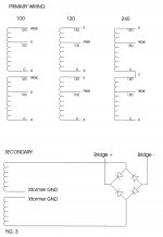
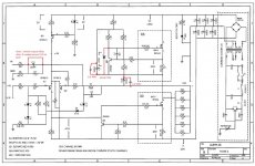
Hi this is from a old service manual I had on my drive & may be useful. Note that this from a Aleph 60 manual. I would try first to x-ref the wiring shown here versus what you have as stock to make sure these are relevant to your amp. Cheers,
Attachments
nothing wrong if he wires them series - antiphase
amp would be just Dodo

Hi Zen Mod, is "just Dodo" a good or a bad thing? If the amp will be as dead as a Dodo, that's bad ...
naah
nothing wrong or damaging will happen
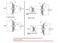
say that you have two primary windings ;
they're A-A' and B-B'
now they're connected (A+B)-(A'+B')
connect them to have A and B' as mains input , with shorting bridge between A' and B
translate your color scheme of wires to that nomenclature and everything is clear
as illustration :
nothing wrong or damaging will happen
say that you have two primary windings ;
they're A-A' and B-B'
now they're connected (A+B)-(A'+B')
connect them to have A and B' as mains input , with shorting bridge between A' and B
translate your color scheme of wires to that nomenclature and everything is clear
as illustration :
Attachments
Hi Zen Mod, is "just Dodo" a good or a bad thing? If the amp will be as dead as a Dodo, that's bad ...
Yep..... anti-phase (also known as "bucking primaries") = Dodo = no output from the transformer..... it won't damage the transfo or the amp, but it sure won't work, either......
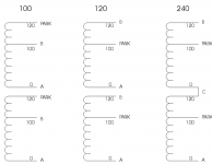
Well the amp has arrived so I'm trying to do the conversion to 240v. Referring to the image, I removed the link from L1 to 3, removed the link from L2 to 1, and added a link from 1 to 3.
The resistance on L1-L2 measured about 17 ohms before conversion, and about 34 ohms after. To be safe I disconnected the power feeds to the amp boards. I put in what I think was a 2 amp slow blow fuse (a spring at one end) and there was a flash at one of the secondary winding connections to the board and the fuse blew.
I set everything back the way it was and connected up with an external 240-120v stepdown transformer and everything is working fine, so it may only have been that the fuse wasn't a slow blow.
Please could someone comment on if my rewiring suggestion looks correct?
Attachments
study this
edit : however , it seems that pcb you're having isn't same as one for which enclosed diagram is ;
good pictures of both upper and bottom sides of pcb will help us , to determine what and where
be careful - if you had flash on any connection from wire to pcb , that means - connection is suspicious
edit : however , it seems that pcb you're having isn't same as one for which enclosed diagram is ;
good pictures of both upper and bottom sides of pcb will help us , to determine what and where
be careful - if you had flash on any connection from wire to pcb , that means - connection is suspicious
Attachments
Last edited:
Looks like I'm welding at the moment ... please help ...
I got the correct 2 amp slow blow fuses, checked all my connections again, each single primary winding resistance is about 1.4 ohms, connected in series, their resistance is about 2.8 ohms, resistance across AC input is about 34 ohms, with the 2 inrush current limiters (ICL) in line. Once again I disconnected the amp boards for safety.
The fuse blew and one of the ICLs sparked. It now measures about 17 ohms instead of its nominal 10 ohm resistance.
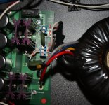
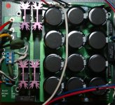
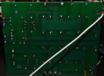
I can't see what is wrong; I have checked the wiring and I definitely have the 2 primary coils in series. The psu board is labelled 2002 PL54PWR5 and is different from the schematic in the manual.
I have included pictures of the top and bottom of the pcb as well as the transformer label.
Please could someone suggest what I'm doing wrong?
I got the correct 2 amp slow blow fuses, checked all my connections again, each single primary winding resistance is about 1.4 ohms, connected in series, their resistance is about 2.8 ohms, resistance across AC input is about 34 ohms, with the 2 inrush current limiters (ICL) in line. Once again I disconnected the amp boards for safety.
The fuse blew and one of the ICLs sparked. It now measures about 17 ohms instead of its nominal 10 ohm resistance.
I can't see what is wrong; I have checked the wiring and I definitely have the 2 primary coils in series. The psu board is labelled 2002 PL54PWR5 and is different from the schematic in the manual.
I have included pictures of the top and bottom of the pcb as well as the transformer label.
Please could someone suggest what I'm doing wrong?
Attachments
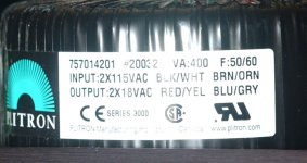
whatever you do , it needs to be black and orange as mains input , with white & brown shorted (connected) together
bulb tester will help only in case of PSU without load , so it's wise to use it , if you're able to disconnect power wires to pcbs
when you measure and confirm proper PSU operation , reconnect wires to channel's pcbs
bulb tester will help only in case of PSU without load , so it's wise to use it , if you're able to disconnect power wires to pcbs
when you measure and confirm proper PSU operation , reconnect wires to channel's pcbs
Thanks Zen and AndrewT for your responses. Is it necessary to have 2 ICLs, on both L and N of the mains input? I can understand why there were 2 when there were 2 primary windings in parallel, but now that there is only one, can I omit one of the ICLs?
yes , you can ........ even if having two is logical - you're still having 110V for each primary winding
Well I connected the transformer as Zen suggested, removed one of the ICLs, put a light bulb in series with the mains as Andrew suggested, and disconnected both amps from the psu.
After a brief glow, the bulb went out. I got + and - 26.9 volts on each side. I see the original design calls for + and - 25 volts per side. When I connected the amps back up, the supply dropped to about 24.6.
Thank you very much to everyone for their help; particularly Zen.
After a brief glow, the bulb went out. I got + and - 26.9 volts on each side. I see the original design calls for + and - 25 volts per side. When I connected the amps back up, the supply dropped to about 24.6.
Thank you very much to everyone for their help; particularly Zen.
now just buy 2 new CL60 , replace them and enjoy (better to have 2 inline for 240Vac)
I'm glad you succeeded in that , basically , easy procedure .
if you're in mood for that , there are few easy and possible steps for further improving of sound ( mainly removing/shorting one cap and bypassing two others with 1u MKC (polycarbonate) and adding one zenner diode , just in case )
you can treat us with few more pictures of beauty in action ...... I'm sucker for pics 😉
- Status
- Not open for further replies.
- Home
- Amplifiers
- Pass Labs
- Convert Aleph 30 from 120v to 240v