I'm working on an experiment where I want to drive a solenoid coil with an audio signal. In the end, I'm hoping to find a way to convert the sinusoidal AC signal into a modulated DC signal that is based on the total (from V+ to V-) amplitude of the audio signal.
For example, if I was to use a signal generator to create a 100hz sin wave with an amplitude from +10V to -10V the output from my circuit would be a sign wave that from 0V to 20V but when there is 0V AC there is also 0V DC.
I understand that without that last bit about both input and output being zero, the circuit becomes a simple DC bias circuit where the AC signal is biased up 10V. This where I come to you folks for any expertise/ guidance you may have.
I'm trying to figure out if there is a way to translate an audio signal into one that can operate a "pull only" type solenoid so that when there is no signal the solenoid is at rest and when the audio signal is applied it moves only in the pull direction. At first I thought this would be achievable if the AC signal was 90 degrees out of phase from the DC one, but I can't figure out the starting condition.
I think basically I want to take the cosin of the audio and then output that with a bias. Is this even possible?
Last edited:
with a standard audio amplifier, the signal moves from positive to negative. Just like you said, a speaker is a moving coil and moves in AND out. I am trying to get this coil to only move in.
with a standard audio amplifier, the signal moves from positive to negative.
I am trying to get this coil to only move in.
With a sine of variable amplitude, you can use a peak detector and add the result
to the input, so the amplifier's output will always be above zero volts.
Last edited:
You probably do not want a "sign" wave to drive a solenoid.
You usually rectify onto a filter cap, to hold/smooth the voltage for a few cycles yet follow the loud/soft of speech/music.
You usually rectify onto a filter cap, to hold/smooth the voltage for a few cycles yet follow the loud/soft of speech/music.
An externally hosted image should be here but it was not working when we last tested it.
Last edited:
when I say solenoid, it's a loose term. consider it an imaginary voice coil without an actual cone or enclosure attached. From what I am reading about a peak detector, That sound like it might be the perfect solution!
Look up a "detector" circuit. Proportional to peak to peak is also proportional to peak at half that amount. SO use the basic detector from an AM radio. A diode. Send your AC through a diode to make pulsing DC. A small cap will filter it to smooth it into more DC-like shape, then the DC voltage will vary along with the AC.
That assumes the AC signal is more or less symetrical, so by chosing one half of the wave form, we are making a DC voltage of half the full p-p amount. But you could just as easily put the AC through a small bridge to create the entire amount. As I read this, you don't really care the amount, you just want signal detected and responded to. You are not looking for some linear response over a spectrum.
But really, your solenoid need not run on the same voltage as the signal. I could have 20v p-p signal, but a 5v relay solenoid, or for that matter a 50v solenoid. All I need is a control voltage made from the AC. A transistor or something can translate that control voltage into work at whatever level you like.
SO far we have a proportional DC voltage, analog varies with the signal. But if all you want is a on/off deal detecting zero, then you can add an op amp or comparator to detect non-zero and toggle to on.
SO we might say run a relay coil with this. And I have say a stereo playing music, like at a restaurant. Then I have a microphone circuit playing into this detector, so all I have to do is talk into the mic, and the signal activates a relay to take over the speakers while I talk. "Smith, party of four, your table is ready."
I once made a cheap project with audio on one channel of a stereo cassette, the other side I recorded a tone when I needed it, the tone I rectified and fed the base of an MPSA13 darlington to control a small relay. SO my music played, and at certain points in the program the tone channel (unheard) activated the relay to control some effect along with the music.
You will have to decide what the minimal threshold is for activation. 1/4v? 1v? 5v?
My description is of a small circuit controlling small currents, but we could just as easily have it control a triac turning a large solenoid off and on. You say solenoid while I am saying relay. Either way the circuit controls an electromagnet, so if your solenoid is doing something other than a relay, fine. Cassette decks often have little solenoids in their transports.
Taking your excellent suggestions, I'm thinking that if I combine these two circuits, I should be able to accomplish my desired outcome.
The first is a peak detector that I found from a post on Circuit Lab and tweaked for good response at the frequencies I'm interested in.

The second if an example of a summing amplifier. I'm not sure what values to use on this one though.

The first is a peak detector that I found from a post on Circuit Lab and tweaked for good response at the frequencies I'm interested in.
The second if an example of a summing amplifier. I'm not sure what values to use on this one though.
> a summing amplifier. I'm not sure what values to use
If in doubt, throw 10K at it.
However I don't see why you need a summing amp. If you need stereo-to-mono, two resistors suffices.
If in doubt, throw 10K at it.
However I don't see why you need a summing amp. If you need stereo-to-mono, two resistors suffices.
I don't see why you need a summing amp.
If you need stereo-to-mono, two resistors suffices.
He'll need to trim the relative outputs to get the best results.
Which amplifier will be used? Some won't drive solenoids very well.
Don't use a coupling capacitor for the peak detector output.
Last edited:
Trim? he just wants to detect presence of signal. The amplifier itself need not drive the solenoid. That is why I suggested developing a control signal from detected audio.


These typical solenoids are AC rated, ie the plunger is attracted inwards regardless of coil current polarity.
Dan.
Like I was saying before, I'm hoping to drive a voice coil type device. It's really not important what I'm driving, The point is that I'm trying to create an all positive voltage audio signal that accurately represents the amplitude of the original AC signal. I don't just want to detect the presence of the signal. It needs to maintain as accurate fidelity to the original as possible. Imagine a speaker that only pulls on the voice coil instead of pushing and pulling. the two circuits I posted look like they are exactly what I'm looking for. The peak detector will bias the original audio signal into an all positive voltage. The summing amp is required because the output from the peak detector has to be isolated somehow from the original audio signal in order to be combined with it. The the two signals are just fed into each other, it acts as a direct bypass and eliminated the peak detection. I would either need the summing amp or possibly I could use an active signal splitter, feeding one output into the peak detector and the other would be directly tied to the second output from the splitter. As for an amplifier, I was thinking that I wouldn't even need an actual audio amp since the signal is DC. I basically just need some fets.
Meter driver.
The guts of a VU meter is a coil (rotating, but could be linear voice-coil). Because this would try to go both-ways on audio, there is a rectifier. And a low-pass filter so it shows the "envelope" not the individual half-waves. Because all mechanical gizmos are "low pass" relative to audio rates, a VU meter just integrates with mass.
I still do not understand why you want to add-back the original audio.
If you truly have 10V peaks one side, and need 20V full-scale, use a gain of 2 DC amplifier. This is what op-amps were MADE for.
Actually it does matter what you are driving for the discussion. When you say solenoid, that infers an on/off control. You want a linear analog system.
I'm trying to figure out if there is a way to translate an audio signal into one that can operate a "pull only" type solenoid so that when there is no signal the solenoid is at rest and when the audio signal is applied it moves only in the pull direction. At first I thought this would be achievable if the AC signal was 90 degrees out of phase from the DC one, but I can't figure out the starting condition.
with a standard audio amplifier, the signal moves from positive to negative. Just like you said, a speaker is a moving coil and moves in AND out. I am trying to get this coil to only move in.
So give us some more (mechanical) detail of what you are trying to achieve.Like I was saying before, I'm hoping to drive a voice coil type device. It's really not important what I'm driving, The point is that I'm trying to create an all positive voltage audio signal that accurately represents the amplitude of the original AC signal.
A loudspeaker causes bidirectional motion because of permanent magnet field and a solenoid coil causes only attraction.
Dan.
For discussion's sake, lets say that I have a traditional speaker motor with voice coil, permanent magnet and spider, but no cone. Instead of a cone, lets say there's a very light weight control mechanism that moves a small lens which then changes the focal point of an optics mechanism. For the effect to work , the lens needs to return to either side of it's focal range, but NOT in the center as the cone would if it was a traditional speaker. When there is no audio, the lens needs to come to rest at displacement zero and then when the music plays it should only have positive displacement. So, I need to convert the +/- audio signal into an all positive signal that is still as accurate (at frequencies of about 100hz and below) to the original signal as possible. It would in effect sound exactly the same if played on a normal speaker, except that the speaker would only be able to use half of it's excursion and the audio amp powering it would only use NPN or PNP transistors instead of both. I hope that helps give a better idea of what I'm going for. Like I was saying it's a bit of a strange experiment lol
OK, like the mirror in a light show laser that moves the beam to the music.
If you are doing something visual with it, I might think the viewer would not recognize it did not "sound exactly" like the audio.
The poor man's version of that was to glue a piece of mirror right onto a speaker cone and aim the laser at it. Oh I miss the old 1960s light shows we had at concerts. Overhead projector, glass tray of colored water and oil all swirling...ahhh.
If you want to know what the positive only half of music sounds like, put a diode in series with your speaker and listen to it. it will be seriously distorted. Even if you went to full wave rectification you still seriously distort the waveform, just as rectifying 60Hz AC makes 120Hz pulsing DC. This would go unnoticed in a moving light show, as it still moves with the music. No one would analytically view it for waveform fidelity.
On the other hand if you want it to be true so you can project a waveform onto a screen or something - like a giant oscilloscope - then fidelity does matter, and then I think you'd have to do something like DC offset rather than half a waveform.
> speaker motor with voice coil, permanent magnet and spider, but no cone
Yes, a meter.
If you do not want the bi-directional, but only the envelope, you rectify. "Meter driver".
So far I think you are over-complicating this. It may get complicated to do *exactly* what you really want to do. But just taking the (half or full) rectified wave, maybe filtering, maybe scaling, is simple.
Don´t overthink it.
Two ways to do it:
1)

The output capacitor will charge to (+V) - (-V) voltage and stay there, until absorbed by load.
2)
Here one capaitor will charge to positive peak, the other to negative peak, both are in series so end to end you get full +V to -V amplitude
3) if only the highest peak AC voltage is needed to drive your solenoid, you may simpy use a full wave bridge rectifier feeding a capacitor:
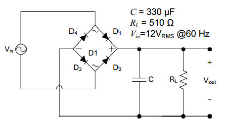
Those are the basic circuits, can be tweaked depending on needed current at the load, or if you do not want to lose diode drop (0.7V each) or whether load is floating o referred to ground, etc. but in general these are the conceptually basic ways to do it.
First two circuits will meet all your demands:
* DC will be generated with a single polarity, your choice
* "it will move only one way", so it will pull solenoid only one way
* ignoring diode drop, which is 0.7V, you will get essentially peak to peak AC value, which you called "total +V to-V amplitude"
For a more accurate o detailed answer, please describe what you are actually going to drive.
The third will meet all, except voltage will be peak of the highest one, positive or negative, and may be enough for what you need.
convert the sinusoidal AC signal into a modulated DC signal that is based on the total (from V+ to V-) amplitude of the audio signal.
You need a peak to peak rectifier, basically, a two diode setup, one rectifying each peak (positive or negative) charging a capacitor or two in series.a way to translate an audio signal into one that can operate a "pull only" type solenoid so that when there is no signal the solenoid is at rest and when the audio signal is applied it moves only in the pull direction.
Two ways to do it:
1)
The output capacitor will charge to (+V) - (-V) voltage and stay there, until absorbed by load.
2)
An externally hosted image should be here but it was not working when we last tested it.
Here one capaitor will charge to positive peak, the other to negative peak, both are in series so end to end you get full +V to -V amplitude
3) if only the highest peak AC voltage is needed to drive your solenoid, you may simpy use a full wave bridge rectifier feeding a capacitor:
Those are the basic circuits, can be tweaked depending on needed current at the load, or if you do not want to lose diode drop (0.7V each) or whether load is floating o referred to ground, etc. but in general these are the conceptually basic ways to do it.
no, you will not have your original sinewave (or any sinewave at all) after rectification.For example, if I was to use a signal generator to create a 100hz sin wave with an amplitude from +10V to -10V the output from my circuit would be a sign wave that from 0V to 20V
First two circuits will meet all your demands:
* DC will be generated with a single polarity, your choice
* "it will move only one way", so it will pull solenoid only one way
* ignoring diode drop, which is 0.7V, you will get essentially peak to peak AC value, which you called "total +V to-V amplitude"
For a more accurate o detailed answer, please describe what you are actually going to drive.
The third will meet all, except voltage will be peak of the highest one, positive or negative, and may be enough for what you need.
- Status
- Not open for further replies.
- Home
- General Interest
- Everything Else
- convert AC amplitude into modulated DC signal