Maybe not the best example worth modifying: the circuit is not very deterministic, regarding the gain or quiescent current for example.
You can find much better circuits, already using Si transistors in the app-notes of Motorola, RCA, Philips and others of the early seventies.
I have given myself a number of such examples, but locating them with the new, improved search function of the forum is a PITA and would take ages
You can find much better circuits, already using Si transistors in the app-notes of Motorola, RCA, Philips and others of the early seventies.
I have given myself a number of such examples, but locating them with the new, improved search function of the forum is a PITA and would take ages
Thanks for the replies.
I have not made a CB yet.
I will search for an amp schematic in that power range that uses Si devices.
HV20821
I have not made a CB yet.
I will search for an amp schematic in that power range that uses Si devices.
HV20821


Finally, I managed to find a few of them:
https://www.diyaudio.com/community/...wer-amplifiers-for-daniel.335079/post-5724404
https://www.diyaudio.com/community/...wer-amplifiers-for-daniel.335079/post-5724404
Why waste time correcting a turd?This will work.
The design is TERRIBLE, it does not even boot-strap the VAS load resistor, no NFB, the works.
Just build a standard modern 6W amp or even better a chipamp, say L1875 or TDA2030, the single ended versions.
MILES ahead.
Feed it 12 to 16V or whatever you have available.
I have one in my bench, fed 12V from an old PC power supply, go figure.
That is what chip amps are for. You need a couple of watts, and just press the Easy button. Might not be able to get them from Mouser these days, but there are plenty of 12 to 18 volt single supply chip amps out there on the surplus market. Can’t get the one you like best there’s more, and not worth faking. I probably have a few each of 10 different part numbers on hand.
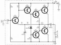
Can anyone help with the conversion of the amp below to Si transistors?
These are great circuits for learning with imo.
Why waste time correcting a turd?
The design is TERRIBLE, it does not even boot-strap the VAS load resistor, no NFB, the works.
Lol, yes, yes and yes 🙂 but on the other hand you learn such a lot playing with circuits like these. This one is very similar to the first amp I ever built. using AD149 outputs. Interesting that this one shows operation from as low as 3 volts, that's germanium for you, it won't work that low with silicon.
One essential modification is to add some emitter resistors , perhaps as high as 0.68 or 1 ohm given its intended use.
Why waste time correcting a turd?
The design is TERRIBLE,
OK, you win 😀 Clipping behaviour is 'interesting'. I still say its great for learning though and it can be improved considerably. A wee bit of NFB added...
Attachments
Now we are getting better 🙂
Please connect R6 not to ground but to hot speaker lead (so it gets bootstrapped yet adding no extra component), a 100 to 220 ohm resistor from Q5 base to +V so you minimize idle drift and reduce sticking when clipping at higher frequencies and resimulate 🙂
Might improve results a little.
Please connect R6 not to ground but to hot speaker lead (so it gets bootstrapped yet adding no extra component), a 100 to 220 ohm resistor from Q5 base to +V so you minimize idle drift and reduce sticking when clipping at higher frequencies and resimulate 🙂
Might improve results a little.
Most probably the clipping behavior is completely different with germanium transistors.I'd say better make that circuit work as it was originally intended to work!
Well...germanium transistors exhibit different current leakage in pnp and npn trz independent of bias, but dependent on VCE.when VCE goes very low leakage goes very low too.
OK, so what's wrong here:
1. The bad clipping is because after we initially reach clipping, Q2 continues to drive even harder, into R7 and forward biasing the collector of Q3, phase reversal. This is partly because R9 is in the wrong place and so is R7. Any CFP needs a pull-off resistor on the base of Q5.
2. R4 limits the gain and that should be handled by R11, which the original circuit did not have. It had no AC feedback, only DC feedback so the gain was poorly defined and would be different for different transistors, L+R channels would not match.
3. The output includes a CFP which may be unstable. You need a Zobel network.
4. When we add bootstrap to the VAS, the extra gain may make the feedback unstable, so we need a compensation cap.
5. 2n2907 is only good for about 700mA so a bigger transistor is needed. 2n2955 are a bit overkill. I would use to-220 like tip42. You won't save any money by using anything smaller.
6. Three diodes is a bit strong for the bias and the idle current a bit too high. Two and a resistor may be OK but then you have two diodes compensation for three transistors, so I think a VBE multiplier is a better idea, ie about 2 and a half diodes worth.
7. The original circuit was intended for a 4 or 3.2-Ohm speaker, not 8. So 0.68 Ohm emitter resistors wastes a bit too much output. 0.33 is a better choice.
8. For silicon, NPN outputs are the natural choice. But today PNP are available and not too expensive.
So that leaves us with some alternatives which the attached examples illustrate.
Attachments
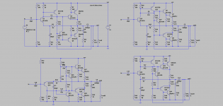
That's a good evolution of the basic design 🙂 It is infinitely tweakable really.
( Only reason I used the 2N's was they are default models and so the sim would click and run for anyone wanting to play)
Common Darlington's could be an option. They seem to work well in the sim and give a good swing with a low component count. A 220 or 470 ohm preset in series with the diode chain could be used to set the bias.
An LM386 8 pin chip amp is another option for a low voltage squawk box/bench amp. Super small and can run off batteries.
This one is safe, simple, proven, and comes from a good source (Philips/RTC/Mullard/Valvo/Elcoma, etc.):

Thanks so much for all the detailed information and suggestions. I am a good tech (retired) and a long time ham op. RF is more my lane but you guys are great and obviously talented.
I have built some chip amps in the past and a 6L6 amp from the #20 RCA Tube manual in 1963 that still works great but not at all up on all the tweeks you guys are. BUT I'm learning again.
Thanks again,
HV20821
I have built some chip amps in the past and a 6L6 amp from the #20 RCA Tube manual in 1963 that still works great but not at all up on all the tweeks you guys are. BUT I'm learning again.
Thanks again,
HV20821
- Home
- Amplifiers
- Solid State
- Convert 6W amp using Ge Transistors to Si Transistors