Hi guys!
I've been lurking around these forums for quite some time now, so i guess it's time for my first post:
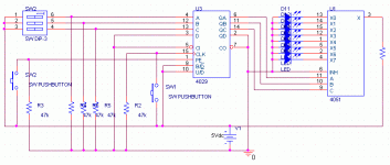
I've been thinking about building a 24 dB/oct Linkwitz-Riley XO with frequency switching. I got the idea from this paper: http://www.rane.com/pdf/linriley.pdf .
I put together a test circuit for the digital controls using a bunch of LED's, a 4051 analog mux and a 4029 up/down counter.
The trouble I'm having is that contact bounce from the switch is making the clock input on the 4029 skip steps in the counting.
I can make it tick ok with an improvised wire-switch and some delicate motor skills😉.
I've tried a simple filter solution from this site: http://www.mitedu.freeserve.co.uk/Design/debounce.htm , but that didn't do any good.
Maybe I didn't wire it up right, i'm still a newbie at this, so i just stuck it in between the switch and the clock input...
Does anyone have any idea of what I'm doing wrong?
Please tell me if you do!
Anyway this is what it all looks like:
The stuff on the far left is just for setting the preset.
(How come you can never get it that pretty on the bredboard? )
I've been lurking around these forums for quite some time now, so i guess it's time for my first post:
I've been thinking about building a 24 dB/oct Linkwitz-Riley XO with frequency switching. I got the idea from this paper: http://www.rane.com/pdf/linriley.pdf .
I put together a test circuit for the digital controls using a bunch of LED's, a 4051 analog mux and a 4029 up/down counter.
The trouble I'm having is that contact bounce from the switch is making the clock input on the 4029 skip steps in the counting.
I can make it tick ok with an improvised wire-switch and some delicate motor skills😉.
I've tried a simple filter solution from this site: http://www.mitedu.freeserve.co.uk/Design/debounce.htm , but that didn't do any good.
Maybe I didn't wire it up right, i'm still a newbie at this, so i just stuck it in between the switch and the clock input...
Does anyone have any idea of what I'm doing wrong?
Please tell me if you do!
Anyway this is what it all looks like:
The stuff on the far left is just for setting the preset.
(How come you can never get it that pretty on the bredboard? )
Attachments
Hi Nuppe,
the standard switch or relay contact debounce circuit uses cross-coupled NAND gates or an SR flip-flop. There are also several R/C delay circuits (Fig. 2) but I've always found them not to be as reliable as the NAND or flip-flop configurations.
The cross coupled NAND is shown in Figure 3 of the following URL:
http://www.elexp.com/t_bounc.htm
Though you will need a different type of switch. It's possible to get push buttons with double throw contacts. You'll also need a 4011 quad NAND gate.
James
Thanks!
I had kindof hoped for some fix for the passive circuit so i could build it without having to get new parts, but as it turns out my buddy had a couple 4011s lying around.
I'm gonna try it out right away! The pushbuttons are no big deal, I'd have to get some new ones to complete the project anyway.
I'll post back with the complete schematic when i've got the actual filters in there too.
(after that there's only building the speakers and amps for my complete triamped system, shouldn't be too big of a deal;.)
/Andreas
- Status
- Not open for further replies.