Here is a simple way to approximate constant voltage or constant current transformers.
Although this is not generally known, ordinary transformers can be used in these roles.
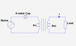
Surprisingly, these two apparently opposed varieties can be implemented in the same way: the addition of a series capacitor in the primary.
Let us deal with the CCT first: when the load current is high enough, the capacitor operates in the regular reactive ballast mode, and the primary current is just linearly scaled by the transformer.
It isn't a true CCT: the actual current will depend on the input and output voltages, but it is nevertheless a useful scheme: it avoids wasting power in a ballast resistor, and makes the transformer very tolerant on the input voltage: it is possible to use a 127V transformer on a 230V mains for example.
Now the interesting part: if the secondary current is decreased below a certain threshold, the primary current will jump to a much higher value than when loaded, and the output voltage will increase to ~125% of the nominal voltage.
What is going on?
The primary and the capacitor are now operating in the ferro-resonant mode, and the output voltage is limited only by the saturation of the magnetic circuit.
The result is a quite acceptable CVT, and the output voltage will be pretty stable within certain limits: a 230V transformer can be made to operate on 127V, and keep its ~125% output voltage.
The only difference is the current: to enter the CVT mode, the output current will need to be reduced accordingly.
The pivotal value of the secondary current is approximately 80% of the transformed ballasting current of the capacitor alone. For example, using a 100nF combined with a 230V-->12V 3VA transformer results in CVT operation below ~50mA and CCT above ~70mA.
The exact values are highly dependent on the transformer.
Some caveats:
-It is essential to use only X-rated capacitors
-In CVT mode, the output voltage is highly distorted (and even asymetrical), the transformer is saturated and tends to radiate high stray fields
-If the capacitor is too large, the maximum rms input current can easily be exceeded, resulting in overheating. It is essential to check the no-load input current to make sure it remains within safe limits.
Although this is not generally known, ordinary transformers can be used in these roles.
Surprisingly, these two apparently opposed varieties can be implemented in the same way: the addition of a series capacitor in the primary.
Let us deal with the CCT first: when the load current is high enough, the capacitor operates in the regular reactive ballast mode, and the primary current is just linearly scaled by the transformer.
It isn't a true CCT: the actual current will depend on the input and output voltages, but it is nevertheless a useful scheme: it avoids wasting power in a ballast resistor, and makes the transformer very tolerant on the input voltage: it is possible to use a 127V transformer on a 230V mains for example.
Now the interesting part: if the secondary current is decreased below a certain threshold, the primary current will jump to a much higher value than when loaded, and the output voltage will increase to ~125% of the nominal voltage.
What is going on?
The primary and the capacitor are now operating in the ferro-resonant mode, and the output voltage is limited only by the saturation of the magnetic circuit.
The result is a quite acceptable CVT, and the output voltage will be pretty stable within certain limits: a 230V transformer can be made to operate on 127V, and keep its ~125% output voltage.
The only difference is the current: to enter the CVT mode, the output current will need to be reduced accordingly.
The pivotal value of the secondary current is approximately 80% of the transformed ballasting current of the capacitor alone. For example, using a 100nF combined with a 230V-->12V 3VA transformer results in CVT operation below ~50mA and CCT above ~70mA.
The exact values are highly dependent on the transformer.
Some caveats:
-It is essential to use only X-rated capacitors
-In CVT mode, the output voltage is highly distorted (and even asymetrical), the transformer is saturated and tends to radiate high stray fields
-If the capacitor is too large, the maximum rms input current can easily be exceeded, resulting in overheating. It is essential to check the no-load input current to make sure it remains within safe limits.
Attachments
Last edited: