Hello DIYaudio community!
I'm currently designing a 3 band parametric equalizer based on the 2nd order state variable filter as proposed by W. Kerman, L. Huelsman and R. Newcomb (State-Variable Synthesis for Insensitive Integrated Circuit Transfer Functions). I like its bandpass response because it is really easy to tune.
I've read articles about the use of this filter topology as a parametric equalizer (to adjust Q, center frequency and boost/cut). I think the most inspiring I read is the one by Ethan Winer (Spectrum Analyzer and Equalizer Designs) and I used his circuit as a basis. Since I didn't want to copy his circuit I studied to see how I could improve it.
One day I read Rane's Constant Q Graphic Equalizers article (http://www.rane.com/pdf/constanq.pdf) and now I'm obsessed with that idea, since I haven't been able to accomplish it. According to the author "The amplitude function must be entirely separate from the bandpass filter function" so I'm using a modified non-inverting SVF and bandpass gain is totally independent from Q.
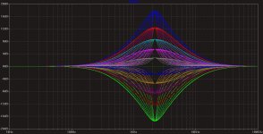
Take a look at the graphs I obtained with LTSpice at various levels of boost/cut, you can see that Q is not constant at all levels. I would like to hear if someone has worked or is working on a similar project to share experiences.
M. Fricke
(Sorry about my bad english)
I'm currently designing a 3 band parametric equalizer based on the 2nd order state variable filter as proposed by W. Kerman, L. Huelsman and R. Newcomb (State-Variable Synthesis for Insensitive Integrated Circuit Transfer Functions). I like its bandpass response because it is really easy to tune.
I've read articles about the use of this filter topology as a parametric equalizer (to adjust Q, center frequency and boost/cut). I think the most inspiring I read is the one by Ethan Winer (Spectrum Analyzer and Equalizer Designs) and I used his circuit as a basis. Since I didn't want to copy his circuit I studied to see how I could improve it.
One day I read Rane's Constant Q Graphic Equalizers article (http://www.rane.com/pdf/constanq.pdf) and now I'm obsessed with that idea, since I haven't been able to accomplish it. According to the author "The amplitude function must be entirely separate from the bandpass filter function" so I'm using a modified non-inverting SVF and bandpass gain is totally independent from Q.
Take a look at the graphs I obtained with LTSpice at various levels of boost/cut, you can see that Q is not constant at all levels. I would like to hear if someone has worked or is working on a similar project to share experiences.
M. Fricke
(Sorry about my bad english)
Attachments
If I can find it and digitize will post it here. If I do not remind me via private message. Good luck -Sum
Magic Filter
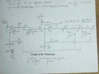
Wish I could claim this one but I cannot. Please thank Mr. Ike Wakibiashi for this one. He put a lot of work into it. Using half way decent parts I have gotten Q=2000 with this set up, WOW!
He gave this to everyone who ask so I pass it freely to this forums users.
Standing on the shoulders of giants, makes me a little taller.😀 Ike was one of those giants.🙂
Attachments
Hi Sum:
Thanks for the circuit, I will start "spiceboarding" the circuit, in previous days I was immersed in the non-inverting SVF equations, I studied a Rane schematic (http://www.rane.com/pdf/old/pe17sch1.pdf) of an equalizer that used this topology. With the common N-I implementation one is unable to achieve Q values lower than 1 (you can using the inverting SVF but then Q is dependant of gain and viceversa). Q can be less than 1 (using the N-I SVF only if):
a) R107 and R108 resistors are not equal but that will modify gain.
b) RC values are not equal (Rane's trick) however I haven't figured out what effect will this imbalance have on frequency and how to tune for the values needed so I will further study it.
Are there any simpler ones than Winer's circuit that allow boosting/cutting, with the frequency and Q all independent(the response frickecello posted is exactly what I need)? I'd like to build 3 single band parametric EQs and cascade them for conceptual simplicity. The amount of opamps used won't be a problem, but I need a design that doesn't use any dual gang pots.
Last edited:
Sorry I forgot to mention that I actually need constant Q as well. I gave the response a better look lol.
The trouble is this is a second order function which means two integrators which leads to a dual pot. Do not use audio taper for frequency. Use a quality linear taper instead and my posted circuit will work fine. You could use a digital resistor ladder with some encoder and control circuit or possibly some device set up as a variable resistor. Linear taper dual gang are not so bad as audio taper pots for tracking and matching the linear ideal values.
Good luck and post if you find a suitable circuit.
Good luck and post if you find a suitable circuit.
- Status
- Not open for further replies.
- Home
- Source & Line
- Analog Line Level
- Constant Q parametric equalizers (SVF topology)