An externally hosted image should be here but it was not working when we last tested it.
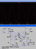
I hope someone can help a bit. I am trying to build a little sinewave generator to play with my new scope. But for some reaon I am haveing a little trouble.
The circuit is powered by 9V, and the top of LP1 (lightbulb) is supposed to be about 2/3 of B+, so 6V. The bulb should be a 60mA device. Now its weekend and I don't have a suitable bulb, I tried the LM317 CCS with a 22R resistor from adjust to output pin, but I suspect the LM317 voltage drop to be too severe, as it is just not working.
Can someone suggest an alternative for a CSS of 60mA... I have some FETs and stuff, but I can't remember the ins and outs, just been out of the hobby for too long.
The bulb is used there as a voltage dependent resistor, not a CCS.
It is thermistor which stabilises the output to below the peak level, keeping the sine pure.
To get it working, using an equivalent resistor (V/I) except that in this operation the bulb current is low - ie doesn't glow.
That will get it working but distortion will be high until you find a bulb or thermistor. Google thermistor.
Have fun!
Cliff
Awesome cliff I will have a quick look, can't believe I wasted a whole weekend chaseing my tail. That will teach me not to make PCB's on a Friday night.
OK, simulation shows your answer to work .
Luckily I put some trimpots in my ciruit after seeing how changeing values in simulation shaped the wave... Soldering iron is allready running, and the LM317 out, now just to scracth around my stuff for the correct replacements. 🙂
Luckily I put some trimpots in my ciruit after seeing how changeing values in simulation shaped the wave... Soldering iron is allready running, and the LM317 out, now just to scracth around my stuff for the correct replacements. 🙂
Attachments
Great stuff!
Sound card on your PC? Download a spectrum analyser and play with circuit values while looking at the spectrum and harmonics.
Time domain ('scope) and frequency domain are both complimentary tools.
I wish I had had the latter when "I were a lad" - it is only in the last decade that I have really come to appreciate (some of) the subtleties.
Just using a USB soundcard and ARTA on a laptop is quite brilliant at the hobby level, and replaces my TEK analyser plug-in ('cost more than my car 🙂 which I never managed to properly repair.
Cliff
Yeah I still need to do the whole PC thing, I haven't even hooked up the scope to the PC yet, it has a USB cable for that.
OK, there might be a problem on the PCB I made, as I am still not getting the sine on the output, BUT, I hooked the probe to one end of the resistor you suggested I put in there, and HEY, its working, probeing around the rest of the board with the other probe, seems to also work, so it might just be a bit of PCB badluck there by the output. Mind you I did have to twiddle my trimpots quite a bit as there is a rather small window on the one, in which things works. One trimpot adjusts the shape of the top of the curve and one the bottom. They would be where R3 and R4 is in simulation.
I feel super stoked right now, this was the Hello World of useing a scope for me.
- Status
- Not open for further replies.
