Going to start a new thread regarding the use of a tail current source in an amp input pair..seems the other thread has taken off on a bit of a tangent, and I'd like to share my findings thus far...
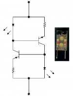
Daniel Rosa had been kind enough to send me a few of these these devices below. I replaced the common emitter resistor in a LPT with one of these in the hopes of:
1. Improved sound, and
2. Lower DC offset at output (currently about 45mV).
Since I did not have the proper size resistor necessary to set the current value I needed, I used a pair of Bourns trimpots set to identical values while waiting on the resistors I need. Orignal emitter current (both transistors together) was 1.6mA, and I adjusted the current source to this value.
I replaced the emitter resistor on only one channel...makes for immedate and telling A/B test between channels with the source component set to send a Mono signal.
Soooo....fire that mother up. I had my scope on the output of both channels. One thing I noticed is that the turn-on thump in the side with the current source is almost non-existant, like the channel with the CS settles down almost immediately. Interesting, but not a real benefit, as the amp has an output relay which remains open for about 5 sec anyway.
Second thing I notice is that the CS had made essentially no difference in output DC offset. OK, maybe a mV or two, but nothing significant. Kinda bummed about that. The current mirror that Douglas Self describes on his site would work, but I cannot butcher the current PC board to that degree.
OK, we know it didn't fix the offset, what about audible improvements?
I spent a good two hours listening, and I honestly can say that there is, to me, no audible difference between the channel with a resistor and the one with the current source. I wanted to hear a diference, but for the life of me I cannot. I know this amp very very well, and any significant change would be glaring to me, as well as the fact that I have the other channel to compare to.
Now, just because I can't hear a difference does not mean that there is no improvement in distortion figures. Unfortunately I have no way to measure THD, and have to rely on my ears.
When I get the rest of my parts in I may very well add the current source to both channels regadless. It certainly does nothing bad, and even though I can't tell a difference, it almost certainly improves CMRR and distortion figures.
Thoughts?
Attachments
EchoWars said:One thing I noticed is that the turn-on thump in the side with the current source is almost non-existant, like the channel with the CS settles down almost immediately.
This is interesting. I remember Prof. Leach, regarding the Leach Amp, saying that a CCS resulted in a turn-on thump, whereas just using a resistor allowed for a thump-free turn-on.
Congratulations on achieving objectivity with your ears.EchoWars said:I spent a good two hours listening, and I honestly can say that there is, to me, no audible difference between the channel with a resistor and the one with the current source. I wanted to hear a diference, but for the life of me I cannot.
Thanks Nelson. I realize expectations have a lot to do with a percieved result. Objectivity is important.
Jam, this is an old Kenwood KA-5500 integrated. The preamp has been extensively modified (trust me, it does not sound like a run-of-the-mill pedestrian integrated anymore 🙂 ), but the amp is still near-stock (sounds just fine). All electrolytics have been replaced with Panasonic FC caps (except the PS filter caps), and was just trying to see if I could reduce DC offset a bit. Thought a current souce for the input pair might do it.
Jam, this is an old Kenwood KA-5500 integrated. The preamp has been extensively modified (trust me, it does not sound like a run-of-the-mill pedestrian integrated anymore 🙂 ), but the amp is still near-stock (sounds just fine). All electrolytics have been replaced with Panasonic FC caps (except the PS filter caps), and was just trying to see if I could reduce DC offset a bit. Thought a current souce for the input pair might do it.
Attachments

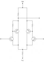
This is what I would suggest for this circuit. Divide the resistor on the differetial into two resistors. At the junction of the two resistors attach a zener to ground. (add a small cap across the zener).
This will regulate the tail of the LTP. You will have to recalculate resistor values for the same current. I tried this on an old Kenwood with a similar circuit to yours with good results.
Regards,
Jam
P.S. I would also remove the VI limiting circuit of the amplifier
This will regulate the tail of the LTP. You will have to recalculate resistor values for the same current. I tried this on an old Kenwood with a similar circuit to yours with good results.
Regards,
Jam
P.S. I would also remove the VI limiting circuit of the amplifier
I can't see how this would work because then you would loose your single "long tail" and the junction of the two resistors would be at AC earth potential so the emitter of the rhs transistor won't be able to feed a signal to the emitter of the lhs transistor and so now you have no negative feedback, so it appears. Wouldn't you still keep some percentage of the resistance common to both emitters?jam said:Divide the resistor on the differetial into two resistors. At the junction of the two resistors attach a zener to ground. (add a small cap across the zener). Regards, Jam
Edit to save face 🙄 Or do you mean to put a second resistor in *series* with the first?

Jam...that is possible, but I'd like to try to keep it simple. Your suggestion would probably mean more hacking od the PC board than I would really like to do.
Isn't there a way to increase the gain of the input stage using two transistors for each side of the LTP? A complementary pair instead of a Darlington?
I've never seen this on an input stage, and I'm not sure how to go about it...Ideas?
Isn't there a way to increase the gain of the input stage using two transistors for each side of the LTP? A complementary pair instead of a Darlington?
I've never seen this on an input stage, and I'm not sure how to go about it...Ideas?
Circlotron,
Sorry if I was not clear but I ment second resistor in series with the first.
Regards,
Jam
Sorry if I was not clear but I ment second resistor in series with the first.
Regards,
Jam
The hided zener...
actualy kenwood as already take care of it.....in the schematic the midle point of this two resistors are conected to the Zener D12 at left near the doted line...
Divide the resistor on the differetial into two resistors. At the junction of the two resistors attach a zener to ground. (add a small cap across the zener).
actualy kenwood as already take care of it.....in the schematic the midle point of this two resistors are conected to the Zener D12 at left near the doted line...
That zener simply supplies 14V for the V+...low noise transistors were tough to come by in the mid 70's that could take the higher supply voltages (+/-44V). The Zener just knocks the + supply down to something the PNP input pairs can handle.
Zener
Sorry...the zener simply suplies the LTP tail resistor as Jam sugest!
Look again! 😉
The Zener just knocks the + supply down to something the PNP input pairs can handle.
Sorry...the zener simply suplies the LTP tail resistor as Jam sugest!
Look again! 😉
6 of one, half a dozen of the other. We said the same thing. The zener is supplying 14V to the emitter...nothing more complex or sinister than that. The regulated voltage may help keep the offset (and emitter current) constant under load, but does little to alleviate DC offset.
No thoughts on using the CFP for the input stage??
No thoughts on using the CFP for the input stage??
when 6 are not half dozen...
As the emiters of the LTP are more or less a diode drop above ground...the voltage that the input pair need to handle is the negativ voltage rail...43 V...the voltage at the zener and the tail resistor only define the current in the LTP and in any way the voltage at the emiters of the LTP
regards
That zener simply supplies 14V for the V+...low noise transistors were tough to come by in the mid 70's that could take the higher supply voltages (+/-44V). The Zener just knocks the + supply down to something the PNP input pairs can handle.
As the emiters of the LTP are more or less a diode drop above ground...the voltage that the input pair need to handle is the negativ voltage rail...43 V...the voltage at the zener and the tail resistor only define the current in the LTP and in any way the voltage at the emiters of the LTP
regards
Can we, like, not obsess about the zener? It's a non-issue. What about using the CFP at the input?
Alright. Assuming stability (oscillation) does not occur, anything else to consider?
I've used CFP's in emitter-follower applications before, but not in a LPT gain stage. At least in emitter-follower applications, stability was not a problem (yes, I know it's a whole 'nother ballgame).
Probably just have to try it out and observe the results.
I've used CFP's in emitter-follower applications before, but not in a LPT gain stage. At least in emitter-follower applications, stability was not a problem (yes, I know it's a whole 'nother ballgame).
Probably just have to try it out and observe the results.
The amp might require more compensation (probably local). Best plan is to build it and see. The reason I am concerned is that a lot of Kenwood amplifiers are on the verge of instability as it is, and any change could easily cause it to oscillate.
Regards,
Jam
Regards,
Jam
Such as a compensation cap on the diff pair? Such as a small ceramic from the base to collector? Sorry to seem dense, but this is new territory for me.jam said:The amp might require more compensation (probably local).
Never noticed instability in any Kenwood except in the ones with blown devices. I have noted that compensation caps seem to be unusuallly small in most Kenwood amps (5-10pf rather than the 'standard' 47 - 100pf).Best plan is to build it and see. The reason I am concerned is that a lot of Kenwood amplifiers are on the verge of instability as it is, and any change could easily cause it to oscillate.
- Status
- Not open for further replies.
- Home
- Amplifiers
- Solid State
- Constant Current Source A/B Test