MEASURE
thats the problem its ultra complicated to measure, i would have to set up like 10 or better 20 test frequencys and measure the gain, i have no source for high accuracy resistors and caps and would have to order them overseas since matching is a big problem when it comes to caps with my test equipment.
I had the hope that spice is finally capable of simulating things halfeway close to reality, and no matter what 12AX7 model I use, the suggested parts values are off -3db at 20Hz
RIAA isn't easy, especially with marginal circuits. You will need to trim, but you can get away with 4 or 5 spot frequencies. All you need is a sound card and a few parts for an interface.
Most critical is getting channel-to-channel correct. Absolute accuracy is nice, but interchannel matching is much nicer.
Most critical is getting channel-to-channel correct. Absolute accuracy is nice, but interchannel matching is much nicer.
Just a little update:
did a Simulation of the audio research SP-8 phono section with the two 12AX7 models i have, the one from Duncan is dead on the published specs, the other model from duncans site is very slightly off but only very marginal (like .3dB)
Eli i will adjust the values in your riaa to get as close as possible to perfect riaa match in the simulation using duncans model, build it and then measure the real life perfomance with like 20 frequency points to see how much difference to simulation there is. I have to look up if my multimeter is accurate enough in ac measurements, otherwise my crappy 100 year old 10Mhz scope will have to do the trick.
This may take a while for part sourcing etc. 4-6 weeks to the first prototype i think. Will the attached power supply work in terms of noise and ripple rejection or would you suggest another solution?
Attachments
RB,
That regulator is (IMO) overkill and 1N4007s are way too noisy. A LR8 in each channel is quite satisfactory and low cost. One way or another, Schottky diodes have to be part or all of the B+ rectification scheme. It's a matter of keeping switching noise out of the B+ rail.
Can you conveniently source a Hammond 260A? That's about as inexpensive a power trafo that can be found, for your "240" V. mains, which will work.
Bridge rectifying 240 VAC gets the job done. What's available from "local" manufacturers? Can a low current 1:1 isolation trafo be sourced, at moderate expense?
That regulator is (IMO) overkill
I thought CRCRC could be enough too + this three pin thingie will be dead quiet i guess , since the circuit will draw only about 5ma for stereo operation, but i have not simulated anything for the power supply yet 😉
Its just for testing, i can try different ps when everything is up and working properly
Small tube transformers in the 250V range are dirt cheap and readily avaible, high precision resistors come from digikey, low tolerance caps will be the hardest to get but i will try nebraska surplus.
Will post the corrected riaa values tomorrow, its nearly 5 in the mornig ... gotta get some sleep
Another Update
Hi all,
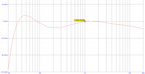
it took a little longer since i had exams at the university last week. Here ist the actual circuit design with the calculated new RIAA values and the RIAA response. I used Duncans 12AX7 model and as you can see there is still a 0.15dB dropoff at 20Hz that i cant solve.
Can someone tell me what the 30uF C2 is for? i guess it has to do with the 20Hz drop and since i know little on tubes i dont really know what it does.
Hi all,
it took a little longer since i had exams at the university last week. Here ist the actual circuit design with the calculated new RIAA values and the RIAA response. I used Duncans 12AX7 model and as you can see there is still a 0.15dB dropoff at 20Hz that i cant solve.
Can someone tell me what the 30uF C2 is for? i guess it has to do with the 20Hz drop and since i know little on tubes i dont really know what it does.
Attachments
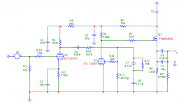
C2 bypasses R3, which is the cathode bias resistor. Without the bypass cap., gain will suffer and the triode's O/P impedance will rise. The phenomenon is known as degeneration. It's a form of local current NFB. BTW, 2.7 KOhms combines with 30 μF. to yield a F3 of 1.96 Hz., no problem there.
IMO, you are making the Eiger out of an ant hill. A drop off of 0.15 dB. at 20 Hz. is irrelevant. Some people would argue that a larger roll off is needed to suppress infrasonic noise. That was actually proposed as a change to the playback curve standard, some time ago.
BTW, what happens when you make C6 220 nF.?
Last edited:
That cap holds the cathode at AC ground. The effective impedance it's bypassing is the 2k7 bias resistor in parallel with the cathode impedance (load resistor plus plate resistance divided by mu), about 1k in this case. So, you've got an unintentional rolloff at 5 Hz or so. Take it up to 100uF; the tradeoff is overload recovery time.
Thanks for the input guys 🙂
Eli, i am not at all worried about the 0.15db since the whole response can vary +/- 0.2 db with 1% caps, at least that is what the simulation says and as long as its within +/-0.25 i see no problem at all.
Increasing C6 to 220nF gives a little low frequency boost anf accuracy is even better now, within +/- 0.6 dB, i will change that value ... i remember i did this when you suggested it first eli but seems i forgot to save the changes in the circuit, thanks for pointing that out.
Does someone see any major flaws in the design or is everything set up and ready to go over to the part sourcing stage?
R13 MUST be 20 MOhms. Otherwise, insufficient grid bias will be present in the 2nd gain block. The biasing technique used here is grid leak, AKA contact. It was chosen precisely because of the light load placed on the RIAA EQ network. Please refer to RCA's 1940s original. The 2 biggest shortcomings of that design are wretched drive capability and mediocre bass extension. The MOSFET buffer deals with drive capability and grid leak, as opposed to cathode, bias deals with bass extension. The values available in modern precision resistors permit improved EQ accuracy.
IMO, you should stop obsessing and build the circuit I originally uploaded. Listen to it, built as shown, before you start modifications. Your ears are far better judges of good sound than any sim will ever be. Look here to obtain builder feedback.
IMO, you should stop obsessing and build the circuit I originally uploaded. Listen to it, built as shown, before you start modifications. Your ears are far better judges of good sound than any sim will ever be. Look here to obtain builder feedback.
Attachments

IMO, you should stop obsessing and build the circuit I originally uploaded
I will, expect results within 3-4 month, got two lencos here that i need to finish first and part sourcing will take some time too.
Thanks for all your help Eli and all 🙂
- Status
- Not open for further replies.
- Home
- Amplifiers
- Tubes / Valves
- Conrad Johnson PV-5, my next project, some simple questions