Hello,
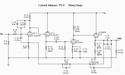
since i finished my pass F5 Monos, i need something to drive them properly, i decided to go with the Conrad Johnsons PV-5, since it has enough gain and a phono stage. It will be my first tube project, but i have an oldtimer at hand who will support me, he is building tube amps for over twenty years so i guess I can try a Preamp with Phono Stage.
I have some minor questions on this circuit:
1. What are the transformer secondary voltages / Ampere Ratings?
2. Which of the powersupply transistors (Q1, Q2, Q3) should be heatsinked?
3. What voltage should the regulated power supply have?
4. Where to get 1% Caps for the RIAA Network? Digikey seems to have none left and my Fluke 29 isnt the most accurate in measuring capacity.
I have attached the schematic at the end.
Thanks for your help
Attachments
Which of the powersupply transistors (Q1, Q2, Q3) should be heatsinked?
Q3 needs a heatsink, as it's the pass element. If airflow is good, I'm guessing Q1 and Q2 are OK, without heatsinking.
Where to get 1% Caps for the RIAA Network?
Try Nebraska Surplus. A mix of NOS mica and 'styrene parts should serve you well.
Try Nebraska Surplus. A mix of NOS mica and 'styrene parts should serve you well.
0.5% micas, this is a DIY heaven ! Thank you so much for the info.
2 problems solved, two remain : The Transformer voltages, I guess one secondary is 12.6V and the current needed can be calculated quick and easy by summing up the heater currents, but i am searching for 3 days now to get the other secondary and voltage for the plate. I even searched old triad transformer catalogues since the part number is given in the parts list but with no success.
Can anyone else help me out?
Thanks for your help
Well i tried to model the power supply in Microcap to see whats the output voltage of the PSU but i failed, i dont know how to connect the sinus voltage source to the rectifier diodes, and implementing a trafo instead of a sinus source ... no way that i get this done right
I also simulated the phono section of the PV-5 just to see that its like 1db off minimun. Either the tube models are not right or the whole parts list for the preamp is screwed up.
Its nearly 2 o clock in the morning, i spent the last 3 days and nights simulating and researching on this circuit and things just get worse and worse.
I think i reached the point where DIY is not fun anymore
But i came up with a better schematic for the phono section, since the original copy is nearly unreadable.
Attachments
Last edited:
I think i reached the point where DIY is not fun anymore
RB,
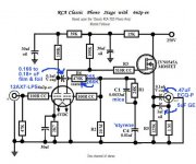
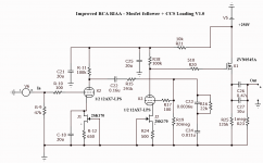
IMO, CJ's design is overly complicated. Also, it uses the out of favor active equalization method. For overload handling and other good reasons, passive EQ is in vogue. I've uploaded a schematic for a tweaked version of the "classic" RCA design that works very well with many MM level cartridges.
An important point you have yet to cover is the sensitivity of your power amps. What sort of drive voltage at the I/P causes full power O/P to be produced? It's quite possible that you don't need any gain whatsoever in the line stage.
Attachments
Thanks for cheering me up 🙂
The F5s need about 6V-7V input for full output swing, so i need a total gain of roughly 65dB from the preamp including , 40dB from the phono stage, another 25db from the line stage, I just listen to vinyl so the line stage is only needed to amplify the phono section, no high level sources here.
I know passive EQ is hip at the moment... but ... well there are many good sounding active EQ circuits out there too.
I just obtained the schematics of the premier 3, including all node voltages, might give it a try, but it think ill have to get some sleep first and think this over again.
I might just get a pearl two and use a single opamp as linestage... naaah, i dont want that, i'd really like to give tubes a chance for my next project, choices choices choices and i just dont know which way to go.
I need : 65db-70db gain, MM compatibility, Riaa Accuracy +/- 0.2dB, proven design with easy to source parts, pre and linestage using the same power supply and a knob to control the volume and low distorsion (below 0.1 or better) since my speakers are not really effective (89dB) and output should be phase correct and contain absolutely no DC since F5s are direct coupled.
But for now, its bedtime
Last edited:
RB,
The tweaked RCA circuit yields approx. 45 dB. of gain. You can easily get the remaining 20 dB. from a resistively loaded common cathode ECC99 section. What's the I/P impedance of a F5?
The tweaked RCA circuit yields approx. 45 dB. of gain. You can easily get the remaining 20 dB. from a resistively loaded common cathode ECC99 section. What's the I/P impedance of a F5?
The tweaked RCA circuit yields approx. 45 dB. of gain. You can easily get the remaining 20 dB. from a resistively loaded common cathode ECC99 section
That sounds interesting, tell me more. The Circuit looks really nice, what about RIAA accuracy
Do you have a link to some example schematics for the ECC99, this could mean i can get a fully functional preamp with just 3-4 tubes, if the output phase is correct and not inverted, i am in.
BTW, is it neccesary to keep the Phono tubes shielded or can they be put on top of the case to shine in all their beauty (PS will be in an external shielded case)?
Sorry for all these simple questions, i am still learning a lot and am happy that i finally understood the basic principles of amplification and just recently got my first scope and function generator.
Its 101KWhat's the I/P impedance of a F5?
P.S: Just found this simple linestage with the ECC99, but no gain is mentioned
Attachments
Last edited:
The Circuit looks really nice, what about RIAA accuracy
RIAA accuracy is good. If you are fanatic, use plastic film, adjustable caps., as shown here, in the EQ network, to achieve "perfection".
Do you have a link to some example schematics for the ECC99, this could mean i can get a fully functional preamp with just 3-4 tubes, if the output phase is correct and not inverted, i am in.
Common cathode cathode topology inverts absolute polarity. So, constant current source (CCS) load each ECC99 section and cap. couple the plates to transformers, which allows you to make the line section non-inverting, end to end. The MagneQuest model B7-10K:10K seems suitable. The step down B7 models are also interesting. You may be able to get something suitable from Sowter in England, which is closer to home.
But isnt the Mosfet of the MM Pre a source follower and inverts the signal, this is fed to the first half of the ECC99 which is non inverting and the last ECC99 is a cathode follower which inverts the already inverted signal and in the end i have a nice noninverted signal.
I dont mind to have inverting and noninverting stages mixed as long as its noninverted in the end.
Thanks for your help Eli. Things are slowly clearing up.
I dont mind to have inverting and noninverting stages mixed as long as its noninverted in the end.
Thanks for your help Eli. Things are slowly clearing up.
All (cathode, source, and emitter) voltage followers are non-inverting. The tweaked RCA circuit has 2X inverting (common cathode) gain stages and a non-inverting source follower. So, absolute polarity is retained, end to end.
Yes, i know ... but at 6'0 clock in the morning after beeing awake nearly 18 hours i guess i start to get a litte inattentive 😱
I found out that i used the wrong 12AX7 models for the spice simulation, had to use the ones with grid current, suddenly all simulations became somewhat more realistic.
I modeled the improved RCA circuit you posted to fiddle around with the RIAA values a little, well what can i say, i got it to under +/- 0.1db accuracy so i am pretty sure +/- 0.2db can be achieved with 1% parts and a little value tweaking.
What bothers me is : In the simulation (6mv p-p input) THD is around 0.75% and IHD (mostly second harmonics) is 0.64% is this a realistic figure, any way to improve the distorsion charachteristics? I tried around a little with negative feedback and differrent plate resistor values but got little to none improvement.
I guess i will build the phono stage first and the linestage somewhat later, still havent found a nice noninverting not overcomplicated design, you find a lot of schmematics on the net, but little info on thd and other specs.
PV5 questions...
Hey Raz!
You may want to take a look at the Audio Research SP8 RIAA stage - this is known to be pretty accurate to RIAA specs and is good sounding.
Here's the SP8 schematic...
http://www.arcdb.ws/SP8/ARC_SP8MKII_Rev7_schematic1.gif
Here's a great write up on modifying a ARC SP3 - consider the Phono stage mod for your CJ...
http://www.curcioaudio.com/SP-3 Mod Documentation.pdf
Good luck and hang in there - these preamps can sound fantastic if carefully revived and modified.
Jaimo
You may want to take a look at the Audio Research SP8 RIAA stage - this is known to be pretty accurate to RIAA specs and is good sounding.
Well that looks interesting too, enough gain, active feedback riaa, but the PS looks more complicated then the whole amplifier 😱
But the specs and the schematics look great, love it when they have component values and power ratings, guess i will throw this in the simulation tomorrow and learn learn learn.
What bothers me is : In the simulation (6mv p-p input) THD is around 0.75% and IHD (mostly second harmonics) is 0.64% is this a realistic figure, any way to improve the distorsion charachteristics? I tried around a little with negative feedback and differrent plate resistor values but got little to none improvement.
THD levels below 1% are hard to detect, when listening to music. That's especially true when the bulk of the distortion is 2nd order. AAMOF, it's euphonic. 😉 If you're going to get involved with tubes, learning to trust your ears is a big part of the experience. An easy way to slightly reduce the THD of the tweaked RCA circuit is to constant current source (CCS) load the 2nd gain block at 900 μA. Overall gain will increase a bit too.
I guess i will build the phono stage first and the linestage somewhat later, still havent found a nice noninverting not overcomplicated design, you find a lot of schmematics on the net, but little info on thd and other specs.
Check out Bruce Rozenblit's "grounded grid" out. It's non-inverting and has a decent sonic reputation. Don't build with 12AU7s, as that type's non-linearity might be problematic. Increase the heft of the heater supply and build with a tube from the 12BH7/6GU7/6FQ7/6CG7 group. The signal path parts values don't change.
First of all i want to say thank you for all of you supporting me and pointing me to the right direction, especially you Eli.
It seems that i made a little a little mistake while simulating the THD, i have only run the simulation for 5 cycles = 5ms, but in this time the coupling cap is still charging. I extended the simulation to 100 cycles, THD is now 0.064%.
I also added CCS Loading with jfets to both tubes since i read lots of positive things about it, nothing fancy just a jfets + resistor.
The new schematic is attached, could you have a look at it if everything is ok?
I have not made up my mind on the power supply yet but i think i will use the 190V-320V regulated one from Rainer zur Lindes book (its powerful enough to power the linestage too) and the usual 3-pin regulator for the heaters.
About the linestage : Still looking for options, i have found no schematics for the "grounded grid", but a lot of hong kong ebay sellers offering kits for it, can you supply a schematic for it? Another option would be to take out the RIAA equalisation from the phono circuit, lower the gain and use the same topology with the mosfet follower for the linestage... hmmm sounds intresting, i think i will simulate that next
Attachments
RB,
That schematic is dead wrong. If you want to CCS load the 2nd gain block, replace R18 with a CCS set at 900 μA. Cascoded DN2540N3s should do nicely. I'd leave the 1st gain block exactly as RCA set it up, towards the end of the 1940s. 😉 The FETs under the cathodes must go.
Constant current devices (sources and sinks) are used to replace load and tail resistors.
Don't give Chinese thieves business! The GG line stage is Bruce Rozenblit's intellectual property and his web site is here.
You don't want CCS in the cathodes of those tubes- quite the opposite, you want to have a constant voltage. You have the first stage cathode bypassed (though you may want to check that value) but not the second. Needless complication- use bypassed resistors or diodes. Calculate carefully the output impedance of the first stage, since the RIAA equalization will depend on it.
The second stage could use a CCS in the plate to linearize it a bit. That's probably the dominant distortion source.
edit: I see Eli got there first.
The second stage could use a CCS in the plate to linearize it a bit. That's probably the dominant distortion source.
edit: I see Eli got there first.
Well maybe i have been playing to much with jfets in the last month, tubes are still new land for me. So back to the original posted schematics it is. After simulating 100 cycles on the original circuit THD is much lower then 0.75% ao will so the safe route and build is as recomended.
The one big problem i have left is the following : i have two 12ax7 models (both from duncans site) but they behave quite different and i must use completely different RIIA values to get the curve right. The questions is : which model to trust?
30uF is suggested in the original schematicYou have the first stage cathode bypassed (though you may want to check that value)
The one big problem i have left is the following : i have two 12ax7 models (both from duncans site) but they behave quite different and i must use completely different RIIA values to get the curve right. The questions is : which model to trust?

- Status
- Not open for further replies.
- Home
- Amplifiers
- Tubes / Valves
- Conrad Johnson PV-5, my next project, some simple questions