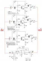
Hi, i want to make a pedal for my guitar with those 4 boosters combined together (signal, bass, treble, frequency) but i don't know if i connect all inputs at the same jack and all outputs of the 4 circuits to the same jack, it will work or i have to make a different "wiring" to use all circuits for the same input and output?
in the attached photo you'll see exactly what i want to do, in explain i want all 4 circuits to receive the signal from my guitar at the same time and to be able to make adjustments and hear them in the output. im not sure what informations i have to give you..tell me more, any help is appreciated!
Attachments
At the output, at least, you would need some type of summing circuit. It's possible that resistors alone, would work. If not, you can use an opamp summing amplifier circuit.
For each circuit's input, I'm not sure. You might want a buffer amplifier for each one. Otherewise, the input impedances would all be in parallel and might be too difficult to drive.
You can find simple opamp circuits for a summing amplifier and a buffer in these classic app notes:
http://www.ti.com/lit/an/snoa621b/snoa621b.pdf
http://www.ti.com/lit/an/snla140a/snla140a.pdf
(Note that you would want to use modern op-amps, instead of the ones depicted.)
Last edited:
scroll down, at bottom, last shown curcuit, audio mixer
Transistor tutorial Audio Amplifiers, Part 5
Transistor tutorial Audio Amplifiers, Part 5
thanks for the responds and the help! So the opamp summing amplifier that gootee says is the same as audio mixer from tinitus..right? then the output is covered..for the input i checked for buffer amplifier and i think the complete circuit will be very big, is there any other way to deal with the input?
dont know the answer
but shouldnt a modern effect pedal unit have buffered low impedance output ?
and you might want some bypass switches
and I overlooked it...maybe it would be good to have input booster/pre, with att pot
maybe with splitting buffers 😀
but shouldnt a modern effect pedal unit have buffered low impedance output ?
and you might want some bypass switches
and I overlooked it...maybe it would be good to have input booster/pre, with att pot
maybe with splitting buffers 😀
For the input, you could try a summing circuit, but without an active device. i.e. Just try a series resistor for each input, say around 33k, with all four 33k resistors joined at their downstreem ends, and then a resistor to ground from that point, maybe another 33k. That would cut each one's level in half. You can probably just try it and see what happens. The resistor values will probably have to be adjusted. Maybe you could use a 100k pot (wired as a variable resistor) in series with a 10k (or ?) R, in place of each series resistor, and another pot in series with an R to ground from their junction, at least just to experiment. Or you could even use it that way, since you'd essentially have a master level control plus four separate ones. Then, if needed (maybe for low output impedance to the next stage, or to get the right level), you could still keep most or all of that and just add an opamp or transistor buffer or amp.
The circuit would not be large. You can get two or four opamps on one chip. And resistors are very small. The schematic would be much larger than the built circuit. I would probably want a separate input amp for each signal, each with adjustable attenuator, and then a summing amp, then maybe a master adjustable attenuator, then an output amp or buffer.
The circuit would not be large. You can get two or four opamps on one chip. And resistors are very small. The schematic would be much larger than the built circuit. I would probably want a separate input amp for each signal, each with adjustable attenuator, and then a summing amp, then maybe a master adjustable attenuator, then an output amp or buffer.
Last edited:
usually they would just be seperate units mounted on a pedal board, and mounted in series
not that I like the series connection very much
if it is still for pedal use, maybe it would make sense to build the effect pedal units as seperate units
what you then need is a small control preamp with the inputs for all, and with all the summing buffers, low impedance output, etc
this preamp could even function as regulated power supply brick for your other pedal effects
and it could be built with genuine pedal volume
so basicly Im suggesting to focus on a real pedal preamp first
and the pedal effects comes second
ah, I forgot
when we talk effect pedals, its called blend
try search pedal blend
or you might be able to blend at least two effect pedals with a stereo balance control
try a stereo pot with one channel reversed, so that one channel goes up, and other channel down
and then feed it into your preamp effect loop
maybe consider to have multiple effect loops, with a switch
but having too many control knobs and options is really just a pain
better when its simple easy and fast
- Status
- Not open for further replies.
- Home
- Live Sound
- Instruments and Amps
- Connection for 4 booster circuits?