away to try the next circuit.
reversed power does not look right.
The 470r is dropping 4V13 and the IR is getting just 0V7. Current draw ~8mA
reversed power does not look right.
The 470r is dropping 4V13 and the IR is getting just 0V7. Current draw ~8mA
Last edited:
If you want I can power mine up and take a scope shot of the output. Should be very distinct and clear with a full 5 volt swing. I'll wait and see what you come back with.
will try +5V to pin1 and use pull up on pin3, i.e. 10k pin1 to pin3
the excessive noise has gone.
I can clearly see a complex sawtooth type waveform @ ~1MHz, DC level 4V22
button pressing modulates that DC level bringing the reading down to 4v20
The spiky modulation cannot lock in.
The 1MHz signal has a blip every fourth cycle and on each twelfth cycle the blip goes deeper
Moving the 10k from pull down to pull up has reduced the noise and subsitutued that 1MHz
Last edited:
If it's not worked as I drew then you must try every configuration.
The receivers normally draw only a couple of ma so that's the first easy test. If it's dropping a lot of volts over the 470 ohm then it's the wrong connection.
The receivers normally draw only a couple of ma so that's the first easy test. If it's dropping a lot of volts over the 470 ohm then it's the wrong connection.
I'll away and try applying +ve power to pin3 with the 470r protection and see what pin 1 does.
Pin3 via 470r to +5V0
Pin2 to 0V0
10k Pin1 to Pin3, lots of noise and 0V0 dc 60mVac ~200mVpp
Quiescent current draw down to ~0.9mA
Activating a button shows a deep change in pin1 voltage.
On some buttons I can see a 4v2 squarewave with a coded mark space ratio.
Is this a sign we closing in on a solution?
Last edited:
I'll look in again in a little while...
If you are not getting anywhere then is it possible the receiver has been damaged by an incorrect connection at fullysupply (with no limiting resistor).
Also the value of 470 ohm is just a ball park figure... confirm the receiver actually has around 4 to 5 volts on it. If the receiver draws much over 2 ma then 470 ohm may be a little high so reduce accordingly.
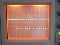
I'll reset the scope to 2V/div and 3ms/div and look see.
1V/div gives a clearer image.
I can't get a steady pattern, but there is a clear ~4V squarewave across the 10k pull up.
quiescent voltage across 10k=0v0.
button pressed gives ~0.7V
This seems to be the biggest and clearest output of the various connection I have tried.
Now, what do I do with R1 R2 that look like 22k each, both going to +5V6?
I'm booked to meet up for an afternoon walk across some of East Lothian.
Bye and thanks to all.
Last edited:
OK... and I can see I must have grabbed the wrong (ch2) probe as it's not compensated correctly for that scope channel. Rise and fall should be crisp.
No ! it was never tested other than using the diode function of the DMM.is it possible the receiver has been damaged by an incorrect connection at fullysupply (with no limiting resistor).
Yes setting the lab supply to overvoltage while monitoring the actual chip supply and setting to 5V00Also the value of 470 ohm is just a ball park figure... confirm the receiver actually has around 4 to 5 volts on it. If the receiver draws much over 2 ma then 470 ohm may be a little high so reduce accordingly.
And I'm gone
Got it working.
Yes, it's a module rather than just a opto transistor.
It starts working with 3.5Vdc and in circuit has 5V54 on pin3, pin2 = 0V0
The 10k pull up on pin1 shows a few tenths fewer volts.
Clear codings on pin1 when buttons pressed.
Damaged a Control board when I connected power to the wrong pair of pins, very big OOPs.
Second board works, select inputs and adjusts volume. But the vol pot must be very sticky in the mid range, it slows down to almost a standstill in both directions.
Checked noise on pins 1 & 2
Pin 2 fed from an RC filter, 47r and 47uF, shows approx 7mVpp sharp pulses and 1.1mVpp wideband noise.
Connected 100nF ceramic across pin3 & pin2, wideband noise reduced to 1mVpp and all pulse noise buried in the wideband.
Moved the decoupling cap to the output of the RC filter on the control board. Absolutely no effect. Proves where decoupling must be located !
This decoupling may have a very slight effect (difficult to read if any change) on the wideband noise of ~0.5mVpp at pin1. The digital output (~3.8Vpp) of pin1 completely swamps the noise which is ~-77dB under the digital signal.
Thanks for all the help.
Last edited:
Hi Andrew, pleased to hear it's all working.
Decoupling... this is what I keep saying regarding ultra low noise regs etc. Great, but the effect is totally lost when connected via some leads, PCB etc to a "noisy" DAC or whatever.
I wouldn't worry to much over noise etc on the IR receiver supply, certainly not at the levels you mention... but it's nice to get it right 🙂
- Status
- Not open for further replies.
- Home
- Source & Line
- Analog Line Level
- connect IR receiver