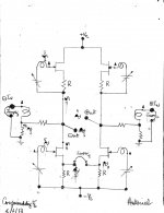
A schematic of the subject balanced amp is attached. The Left and Right channels were joined at the source ports of their lower JFETs [or MOSFETs] to make a differential amplifier [Jumper1 or bridge in place]. This schematic promises vanishing distortion through a loudspeaker. Let us play this game to understand why.
Best regards
- Remove Jumper 1 to give separate diyF6s
- Ground the + and - inputs.
- Make believe that the Left channel has a persitent low frequency oscillation or is motorboating. By contrast, assume the Right channel is absolutely quiet.
- Follow the numbers [0 to 6] on the half shaded sine wave signals.
- Signal 1 starts at the - power output port of the Left amp.
- This Left amp tries to minimize the amplitude of Signal 1 via loop feedback.
- The key is that the simultaneously generated Signals 4 and 6 are out of phase with Signal 1 as the Left amp does its best to minimize the amplitude of Signal 1; which persists in the end.
- Connect a loudspeaker between the power output port of the Left amp and ground. It sings.
- Connect a loudspeaker between the power output ports of the Left and Right amps. It sings.
- Insert Jumper 3. The loudspeaker is quiet. Here's why.
- Signal 5 at the gate of the lower JFET [Left amp] induces Signal 7 at the source of this JFET. Or this JFET operates as a buffer.
- Signal 7 is Signal 8 at the source port of the lower JFET [Right amp]. This JFET operates in the common gate configuration.
- Its output signal is Signal 9 which is in phase with Signal 8.
- Connect a loudspeaker between the power output port of the Right channel and ground. It sings.
- Connect a loudspeaker between the power output ports of the Left and Right amps. In this instance it does not sing. Why?
- Signals 1 and 9 are in phase and most probably are of equal amplitude. The loudspeaker rejects their flow-through.
- The Right amp does its best to minimize Signal 9 via its feedback loop like the Left amp did. But; as long as their are Signals 7 or 8 at the joined source ports of the lower JFETs, there must be a Signal 9 in phase with them.
Best regards
Attachments

Similar, and imo identical to the logic in US 5,376,899. Conjoined twin diyF5s and conjoined twin diyF6s are further applications of your patent.You can use similar logic in examining patent #5375899.
😎
Best regards
however , as every LTP is good only as long Tail is , it needs to be examined how long Tail is in case of Conjoined Twin F6
logic - longer the Tail , greater SUSY is , meaning greater error correction is
complicate it - include looong tail , on expense of third PSU leg

logic - longer the Tail , greater SUSY is , meaning greater error correction is
complicate it - include looong tail , on expense of third PSU leg
Thanks Zen Mod for your analysis. Every extra helps.however , as every LTP is good only as long Tail is , it needs to be examined how long Tail is in case of Conjoined Twin F6
logic - longer the Tail , greater SUSY is , meaning greater error correction is
complicate it - include looong tail , on expense of third PSU leg
Best regards
I look forward to your opinion on its sound. F6 is funny thing. Some folks love it, some folks like it, some folks dont care.
The schematic suggests goodbye to the beloved harmonics DIYers love [and nurture] in Pass amps. It'll sound different from simpler non-conjoiined balanced amps; which are relatively richer in harmonics by comparison. It'll sound great.I look forward to your opinion on its sound. F6 is funny thing. Some folks love it, some folks like it, some folks dont care.
Why bother spend legal fees to patent US 5,376,899 if the perceived harmonics are all that matters to great sound? Mr. Pass taught in it vanishing harmonic distortion; meaning goodbye [or good riddance] to H2 and Hn... Its practical amps sound great without reliance on harmonics. These amps still create harmonics in their subunits like any other; except the harmonics do not pass through the loudspeaker; because of mutual replication of each other's harmonics in both amplitude and phase.DIYers are not the only ones who nurture those harmonics.🙂
The following are the four critical tests which I used to unravel whether a balanced amp has the special performance to reject the passage of harmonics through a loudspeaker but simultaneously pass the parent fundamental frequency.
- Motorboat in one channel [this amp passed]
- Single Ended Input to one channel [current post]
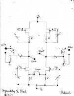
- Common mode fundamental frequency signals to both inputs [homework; unmarked schematic is attached for practice]
- Differential fundamental frequency signals at inputs [homework]
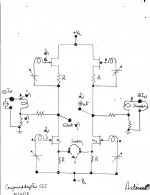
- The rhetoric below is happening simultaneously [in real time] in the semiconductors. I am breaking the operation of the amp in small steps for explanation only.
- Ground the input of the Right channel. Admit Signal # 0 to the input of the Left channel. This is Single-Ended Input [SEI] operation.
- I separated the operation of CTDF6s of processing the Fundamental 1 KHz signal from the resulting harmonic distortion.
- The pictures which depict the processing of the Fundamental Signal 0 only [ SEI] and that of its harmonics [SEIdist] are attached.
- Focus on the amp's operation with fundamental signal only.
- Signal 1 is the amplified input signal 0.
- Signal 1 is returned to the inverting port of the transformer after amplitude reduction to become signal 2
- The algebraic difference betwen signals 0 and 2 [amplitude and phase] generates signals 3 and 4.
- The bottom Left N-JFET buffers signal 4 and generates signal 5 at the joined sources of the lower JFETs.
- The bottom Right N-JFET operates in common gate configuration and amplifies signal 5 to make signal 6 which is in-phase with signal 5.
- Power output signals 1 and 6 are out of phase; or differential. They pass through a loudspeaker connected between the power ports. So this amp is a SEIDO; single ended in and differential output out.
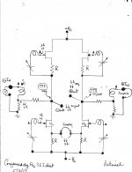
- Focus on the attached picture ending in SEIdist.
- Fundamental signal 0 stimulates the Left amp to generate harmonics at the power output port. I show two arrows pointing down [1h] to imply a second harmonic. This is the original harmonic.
- The Left amp minimizes it by loop feedback; but it still persists in amplitude and phase.
- Harmonic 4h at the gate of the bottom Left NJFET buffers it and generates harmonic signal 5h which is in-phase with it.
- The lower Right NJFET operates in common gate configuration and amplifies signal 5h to generate signal 6h [a copy of 1h] which is in phase with it.
- The harmonic signals 1h and 6h at the power output ports are in phase and most probably of equal amplitude [identical copies]. They do not pass through the louspeaker connected between these two ports.
- Every time I said the Right amp amplifies, it follows that this amp also generates its own harmonics; depicted as 3 arrows in a rectangular box at its power output port.
- So the Left amp now processes this 3 arrow harmonic and generates an identical copy of it at its power output port.
- The 3-arrow harmonic at both of the power output ports of the amp does not pass throught the loudspeaker.
- Points 11, 17 and 20 comprise the key elements of the special value-added performance of this amp. A loudspeaker connected between its power output ports, passes only the differential fundamental signal and simultaneously rejects the flow of the identical harmonics [amplitude and phase] by each amp.
Attachments
- Status
- Not open for further replies.
- Home
- Amplifiers
- Pass Labs
- Conjoined Twin diyF6s