I'm a newbie to electronics and just have a simple question to post. So if capacitors block DC current, and condenser microphones are powered by this DC current, why is there a capacitor before the capsule? Wouldn't the voltage end at the cap? Based off the schematic, the DC current flows through cap C1 (rated at 240pF) then into a 1000M resistor, then into the capsule. I'm confused.😕
You aren't confused (in two senses at least), the schematic is wrong, or you're mistaken. Caps do block DC. Condenser mics do require DC. So there must be a DC path to power the mic.
w
w
The capsule should be the capacitor although 240pF is a bit on the high side.
The resistor is the bias resistor and 1000MegaOhm is bang on target.
The resistor is the bias resistor and 1000MegaOhm is bang on target.
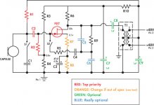
It's a little difficult to see, but you've got a DC path for the 48V via R1 and T1.
For some simple examples of electret preamps take a look at this page on Rod Elliot's site:
Recording and Measurement Microphones
Cheers,
Dave.
For some simple examples of electret preamps take a look at this page on Rod Elliot's site:
Recording and Measurement Microphones
Cheers,
Dave.
Thanks Davey. After some searching I found an article written about how this particular microphone works. I just pasted the first part below so you can read what is being conveyed. I'm in the process of trying to learn some of the basics of electricity and so forth . . . here you go.
How the electronics work
The electronics are comparatively simple. They consist of a single FET that acts as an impedance converter stage, and a transformer that takes care of balancing the output.
Power is supplied on the output jack by the preamplifier, so pins 3 and 7 of the transformer are about 48 V above ground. This means that the center tap of the transformer is also 48 V above ground, and the DC offsets on both sides of the transformer cancel each other out so the transformer doesn’t saturate. So we take the power off the center tap, use C9 to filter any noise or residual signal from it, and then apply it through R1, a very high value resistor, to directly polarize the capsule. We also run it through R10 and C7 to produce a lower filtered voltage that is used to power the front end.
Davey, I was just reading on wikipedia that an electret microphone is a type of condenser microphone, which eliminates the need for a polarizing power supply by using a permanently-charged material. But mine requires a polarizing power supply. Hence the question about how, or which type of current is polarizing the capsule. Man, I'll read the article you referenced, but I'm still confused.
Electret microphones have a built-in JFET amplifier almost without exception (AFAIK) so a supply is still required, although not for polarization.
w
w
I'm a newbie to electronics and just have a simple question to post. So if capacitors block DC current, and condenser microphones are powered by this DC current, why is there a capacitor before the capsule? Wouldn't the voltage end at the cap? Based off the schematic, the DC current flows through cap C1 (rated at 240pF) then into a 1000M resistor, then into the capsule. I'm confused.😕
Not shown in the circuit is a 6.8k resistor (in the mic power supply) from each output pin to +48. So the +48 goes through these resistors and the winding of T1, through R1 to produce the DC bias on one side of the capsule, and through R10 to power the FET circuit. C2 blocks the DC from getting to the FET but passes the audio from the capsule. This circuit is the same as a Neumann KM-84 from the 1970s.
Member
Joined 2007
- Status
- Not open for further replies.
- Home
- Live Sound
- Instruments and Amps
- condenser microphone question