Hey.
I've got problem. I've recently made phantom powered condenser microphone for violin, nothing special, but I must repair the problem as soon as posible, because someone desperately need the microphone.
I've build microphone preamplifier using that site:
Powering microphones
under Balanced electret microphone circuit.
It works well for my needs. Or at least, it worked well until I didn't add MUTE switch. So the problem is I can't get rid of the bang while switching from mute to unmute and vice versa. The switch is DPDT.
If you could give me some advice how to connect the switch(or add some resistors, capacitators, whatever), so there won't be that BANG while switching.
I had tried some connections, but they weren't good.
thank you for help, and I hope you could understand my engilsh🙂
and the circuit is(without switch):
Attachments
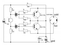
This doesn't look like a good circuit to me. There is dc everywhere and no good place to connect a muting switch as I see it.
well, I think it's good because of it's simplicity and it sounded well too, but this switch has really complicated the whole thing!
I've been searching for orther circuits, but I didn't found anything that is phantom powered and without 198654793 elements🙂 If you've got any alternative circuits I would be very glad to see them!
thanks!
I've been searching for orther circuits, but I didn't found anything that is phantom powered and without 198654793 elements🙂 If you've got any alternative circuits I would be very glad to see them!
thanks!
This looks like an okay circuit to me. You just have to know how to wire a mute switch that doesn't cause a DC offset.
Connnect the positive end of 10uF capacitor in series with the switch, and let's see, put a 10k resistor across the switch to charge the capacitor when the switch is off so there is no DC offset generated when it is turned on.
Connect the unconnected end of the capacitor to the bottom point of the mic element, and the "far" (unconnected to the capacitor) end of the switch to the other connection on the mic element. Or, this series cap-switch-resistor device might work as well or better between the bases of the transistors, where there is much less DC offset.
ETA: Your English is good, but if you can't read mine, here's a schematic:

Connect point A to the base of one transistor, and connect point B to the base of the other transistor
Connnect the positive end of 10uF capacitor in series with the switch, and let's see, put a 10k resistor across the switch to charge the capacitor when the switch is off so there is no DC offset generated when it is turned on.
Connect the unconnected end of the capacitor to the bottom point of the mic element, and the "far" (unconnected to the capacitor) end of the switch to the other connection on the mic element. Or, this series cap-switch-resistor device might work as well or better between the bases of the transistors, where there is much less DC offset.
ETA: Your English is good, but if you can't read mine, here's a schematic:
Connect point A to the base of one transistor, and connect point B to the base of the other transistor
Last edited:
Hey!
I test this circuit and it works fine with no pop, but it isn't completely mute(but enough for my aplication). I put it between the bases of the transistors.
Just before I put the circuit board back in the plastic box I tried this circuit without capacitator. I didn't know what is going to start glowing or explode🙂, but I must tried🙂. And it worked very well, no pop and completely(or at least unhearing mute) mute. So, can you tell me, is there anything wrong with what I did? If it isn't, I would stick with resistor and switch(is the 10k resistor even necesary?).
Thank you very much for help!
p.s.:well, i think we understand each other good enough to solve the problem🙂
Very interesting these solution. What component would you have to use for the switch to work through a 5V control signal?
Why do you need a mute switch on the mic? Very few have them, dont see any in studios, thats what the mixer is for.
What You need is a voltage ramp circuit.
Something like this:
Ramped Phantom Power
Some mixers feature something alike. Check on the schematics how it is implemented.
Something like this:
Ramped Phantom Power
Some mixers feature something alike. Check on the schematics how it is implemented.
Two different circuits for mic muting when phantom voltage is present. Either one will work. Note that neither circuit provides infinite muting (complete elemination of the mic signal), but does reduce the mic signal level substantially, typically greater than 50 dB.
Circuit must be in metal box with box grounded to pin 1
Image
Switch shorts mic audio. Adjust potentiometer for minimum thump when switch is closed.
R1 > 100kohm (exact value not critical)
Image
C1=2200uF, 6Vdc for 150 ohm mic
C1=1000uF, 6Vdc for 600 ohm mic
This circuit must be in a shielded enclosure.
I used the above many times with good results.
From Shure.
This is a circuit for a balanced electret microphone. Yours is a phantom powered condenser microphone. Electrets don't need phantom power. Yours does. How can it possibly work?
Why do you need a mute switch on the mic? Very few have them, dont see any in studios, thats what the mixer is for.
hi cbdb
For wireless microphones in live, films or theater, autonomuos instalation (there are swicht base availables, even mic with swicht like AKG D95 S ) where the mixer console is not than relevant like in a Studio.
Electrets don't need phantom power
It's not called phantom power but a lower BIAS Voltage.
On computers it's usually something between 3-5V fed via a resistor.
Yes it is. And see what PRR says above. There is a FET inside the capsule, they typically operate at around 3 volts.
I don't understand why a mute switch would cause some noise here unless it is switched to ground. This is a nogo as phantom power is applied. The only way to add a mute is to short the ballanced output (short hot and cold), not to ground! The 48V is on both signals (via 2x 6.8K resistors) and it is exactly the same so shorting the signals here is never an issue (unless there is an unballance in the mic, in this case the transistors need to be matched).
Last edited:
- Home
- Source & Line
- Analogue Source
- Condenser microphone and mute switch