To add to Charlie's points, It's not a lobe that is created by non-coincident drivers, but two "holes" in the response (one up and one down in the plane of the two drivers) - Holes and lobes are quite different things. These holes have little effect on the power response since they are so small. They will move in and out in opposition with the driver spacing and they will move up and down in synch with the inter driver phasing at the crossover point. The MTM situation will create vertical lobes from the two M drivers, but no "holes".
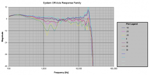
Let me give you a concrete example of what I am talking about when I say there will be response problems in the vertical direction for an MTM caused by interference between the M drivers. As Earl pointed out, these cause nulls or "holes" in the response. The attached plot is the vertical response -30deg to +30deg (see legend) of an MTM system I built comprised of two 7" woofers (Exodus Anarchy) and a very small compression driver+horn tweeter (from DIYsoundgroup, NLA) sandwiched in between them as tightly as possible. The system was crossed over around 2k-2.5kHz IIRC. You can see the hole (looks like 2 dips really) from about 800Hz to about 2.5kHz reaching over 12dB deep at 30 degrees off axis.
If the rest of the system's frequency response was down 12dB at 30 degrees off axis that would be fine. It's when only a band that wide (about 1.5 octaves) is up or down by 12dB and the rest of the system is flat, it's less than ideal. If I could have crossed over the M's to the T at 800Hz, there would be no dip. That's what I did in another similar system in which I used a small full range driver as the tweeter and I thought it sounded very nice. I took apart the system used to make the attached plot soon after making these measurements on it. There was no way to "fix" the response problems with the set of drivers I was using (it also had some response problems in the horizontal plane) and it did not sound good to my ears.
The large majority of MTM system I have seen use a crossover point (2kHz or even higher) and/or the midwoofers are too widely spaced apart. Adding yet another pair of M drivers (like the DNA Sequence does, with one on each side of the tweeter in addition to the one above and below it) will only make holes appear in the horizontal responses as well. This results in a very narrow spot in space that has flat response, directly on axis with the tweeter. Moving off axis in any direction will put you into the "hole". This is exactly what happens with large planar/panel systems like the Quads and that was why it was very telling that was shown as a listener comment.
Attachments
Pointing to that paper again I would like ask Charlie and Earl to comment on the last two examples shown in the paper, a 3-way concentric array. It's not your avarage Joe's design, instead Nils took the effort of making a proper horn/waveguide for the tweeter and of course he used a dedicated Horbach-Keele FIR-Crossover which is known for giving excellent results when properly designed, much better than any analog/IIR crossover, let alone a passive speaker-level one.
I applaud the desire to test this theory. It seems overly complicated, and in the realm of the fiddly.
Synergy horns make an arrangement like this work, but they're deceptive.
The alignment of drivers, limited bandwidth of their operation and necessary equalization for smooth frequency response are complications.
An elegant solution has already been demonstrated by Dr. Geddes.
Sometimes, more is just more mess.
Sent from my Nexus 6 using Tapatalk
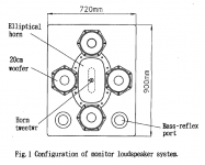
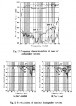
FYI, this 1995 AES paper describes a system that's very similar to the one(s) being discussed in this thread.
Attachments
FYI, this 1995 AES paper describes a system that's very similar to the one(s) being discussed in this thread.
Judging by the horizontal and vertical response plots, it looks to me like the crossover point is below 1kHz, maybe around 700 Hz. I don't have an AES subscription so I can't read the full paper. Keep in mind I didn't say the MTM concept (or even multiple drivers around a central one) could never work, only that you need to cross over very low in order for it to do so. This is usually about one octave lower than you can go with your usual 1" dome tweeter, that is to say you need to cross over around 750Hz (a bit lower is even better). At this wavelength the M-M driver spacing can be made about 1/2 wavelength or less, and the off axis holes are minimized.
Pointing to that paper again I would like ask Charlie and Earl to comment on the last two examples shown in the paper, a 3-way concentric array. It's not your avarage Joe's design, instead Nils took the effort of making a proper horn/waveguide for the tweeter and of course he used a dedicated Horbach-Keele FIR-Crossover which is known for giving excellent results when properly designed, much better than any analog/IIR crossover, let alone a passive speaker-level one.
From what I know about Horbach-Keele systems, I am impressed. This is another good example of what it can do. Although in general I am not a fan of FIR, this particular use of that type of filter is really interesting. The last heatmap in the whitepaper looks very good.
I wasn't considering this kind of crossover when commenting on the other systems. I was able to see from pictures of the DNA Sequence the the crossover is passive, so H-K wouldn't apply there. Alas, the H-K crossover is probably out of reach (technically) of 95% of DIYers.
I also would like to point out that I am confident that the techniques shown here could be made to work reasonably well. I have no confidence that they would be an improvement on the classical approaches in term of directivity control, power handling or cost. I think that best case they might approach a well engineered two way waveguide woofer system in all of those areas, but I see no reason to believe that they would best the older designs in any of them.
I was thinking about this issue today. I have been "into" directivity for more than 30 years. far longer than most designers. I was the first to look at "horns" not as "loading" devices, but as directivity controlling devices, that was nearly 30 years ago. I have continued to look at all aspects of directivity and how one might achieve control over as wide a range as possible. In that time nothing has stood out to me as besting the waveguide approach. It is cost effective with a very high level of control. Higher DI at ever lower frequencies than is effective for a reasonable size waveguide is an interesting problem, and again, one that I have worked on in some depth. My SPEAK program from many decades ago could analyze all of the designs being shown here and still we don't see any in the marketplace. I keep coming back to nothing beats a big woofer for high DI to ever lower frequencies. A ring of smaller drivers will lack the power, and control of the larger device even if it has comparable DI. It unlikely that its frequency response will be as good, but these days with DSP that is not such a big issue.
I'm not saying that nothing will ever "best" the classic two-way with a waveguide, I just haven't seen it yet.
Last edited:
I also would like to point out that I am confident that the techniques could be made to work reasonably well. I have no confidence that they would be an improvement on the classical approaches in term of directivity control, power handling or cost. I think that best case they might approach a well engineered two way waveguide woofer system in all of those areas, but I see no reason to believe that they would best the older designs in any of them.
I was thinking about this issue today. I have been "into" directivity for nearly 30 years. far longer than most designers. I was the first to look at "horns" not as "loading" devices, but as directivity controlling devices, that was 27 years ago. I have continued to look at all aspects of directivity and how one might achieve control over as wide a range as possible. In that time nothing has stood pout to me as besting the waveguide approach. It is cost effective with a very high level of control. Higher directivity at ever lower frequencies than is effective for a reasonable size waveguide is an interesting problem, again, one that I have worked with in depth. And I still come back to nothing beats a big woofer for high DI to ever lower frequencies. A ring of smaller drivers will lack the power, and control of the larger device. It unlikely that its frequency response will be as good, but these days with DSP that is not such a big issue.
I'm not saying that nothing will ever "best" the classic two-way with a waveguide, I just haven't seen it yet.
Earl, just curious how you see dipole systems in terms of directivity control. Obviously they emit to the rear - is that an undesirable characteristic in your opinion?
I have looked at and built dipoles many times and here is what I believe:
First, I have little to no confidence that higher DI below about 500 Hz is going to be a significantly audible aspect of a complete design. I am doing some subjective testing now that is showing that localization of a complex tone is dominated by the higher frequency harmonics masking the localization of the lowers ones. In other words, if you get the HFs right (>500 Hz.) you have pretty much solved the problem.
Second, until recently correcting the huge efficiency loss of a dipole required complex electronics and more amplifier power to achieve. In the past this was a major cost inhibitor. With modern low cost DSP and power amps the electronics is becoming reasonable, but when I was looking at this problem it was still not cost effective to make high power dipoles.
One can throw away the high efficiency of the waveguide to match the low efficiency of the dipole and do this problem passively - we see that in the market - but I question the logic of this situation. To me high efficiency is a good thing, not to be wasted. Throwing it away to achieve a higher DI below 500 Hz just does not seem wise to me.
Shortly I will be auditioning a dipole system that does just what I described and doing measurements. That will tell me a lot about how effective this approach is.
Hmm, interesting. I'd like to learn more about that. It's good to have this kind of information when thinking about design tradeoffs.I have looked at and built dipoles many times and here is what I believe:
First, I have little to no confidence that higher DI below about 500 Hz is going to be a significantly audible aspect of a complete design. I am doing some subjective testing now that is showing that localization of a complex tone is dominated by the higher frequency harmonics masking the localization of the lowers ones. In other words, if you get the HFs right (>500 Hz.) you have pretty much solved the problem.
There are certainly design approaches for dipoles that do not need to suffer so much "dipole loss". These involve using 4-way or 5-way systems and using the driver where its output is highest - around the dipole peak but not too far below. Since the response drops off at only 6dB/oct below the peak you can certainly go 1.5 octaves below. With the right driver you can use it above the dipole peak as well, about half an octave or more, depending on what the driver is doing there. Because the dipole peak is +6dB with respect to the infinite baffle response it is making up for both the lower power response of a dipole (vs a monopole) and the dipole front-to-back cancellation losses. The designer needs to choose their drivers carefully and manufacturer specifications really only hint at whether a particular driver will work and over what bandwidth - you have to buy and measure them.Second, until recently correcting the huge efficiency loss of a dipole required complex electronics and more amplifier power to achieve. In the past this was a major cost inhibitor. With modern low cost DSP and power amps the electronics is becoming reasonable, but when I was looking at this problem it was still not cost effective to make high power dipoles.
One can throw away the high efficiency of the waveguide to match the low efficiency of the dipole and do this problem passively - we see that in the market - but I question the logic of this situation. To me high efficiency is a good thing, not to be wasted. Throwing it away to achieve a higher DI below 500 Hz just does not seem wise to me.
Shortly I will be auditioning a dipole system that does just what I described and doing measurements. That will tell me a lot about how effective this approach is.
DSP is helpful because there are many corrections to be made to the driver and system responses. I'm sure that you can imagine that, with a 4- or 5-way system, there are many, many filters! But IIR filtering is all that is required - there is no need far any fancy DSP tricks. DSP is just an economical (and physically small) way to implement so many filters, and today's DSP units bring that capability to the masses.
Hmm, interesting. I'd like to learn more about that. It's good to have this kind of information when thinking about design tradeoffs.
I create a signal that is a model of a musical instrument, in this case a cello.
I pan the image right with intensity, except that I can place individual harmonics in different directions. The image tends to stay with the harmonics as long as the total SPL does not shift too much. The reason for a higher DI is to avoid early reflections which can interfere with the image stability. If the image is dominated by the higher frequencies then the need for a higher DI at lower frequencies is not very strong.
I can, but have not tried panning with delay. That will be interesting as well.
What do you think of this idea.. that midrange could be propagated around the outside of a waveguide, with the shape of its wavefront matching that from the mouth of the waveguide but external to it, with its radiation space confined to 2x that of the waveguide space minus the waveguide space (ie: a DI match) at the crossover. The midrange pressure at the crossover would support that of the tweeter to perhaps eliminate some of its diffraction after maybe minimising the tweeters mouth size. Below this the mid radiation space could open up over the waveguide's space hopefully at a low enough frequency.
I modeled this many years ago and found it extremely difficult to get anything that I wanted to build, except in one case. But in that case things did not work nearly as well as the sims suggested so I just never pursued it any further.
- Status
- Not open for further replies.
- Home
- Loudspeakers
- Multi-Way
- Concentrically-arranged mids around a tweeter