Hello. I am assembling a homemade two-way speaker with an active crossover and would like to add low-frequency boost to achieve interesting sound at low volume levels. Having studied the topic a little, I came to the conclusion that I need a limiter or a compressor. Inspired, I turned to a group of audio enthusiasts with a request to help find a simple compressor circuit. This is a circuit on an optocoupler and a dual operational amplifier, quite simple. I was able to make a primitive printed circuit board and began testing it with only a superficial understanding of how to set it up. After fiddling around for several days, I realized that nothing was working. Since the compressor is quite slow and affects the entire incoming signal, there were volume jumps or a drop in volume in general if a long release was established.
In general, I am interested in portable speakers and have tried many different ones. The models that stood out most were JBL and Harman/Kardon. Their peculiarity is that low frequency compression occurs without any noticeable effect on other sounds, and to be honest I don't really understand how they achieved this. Ideally, I would like to understand their signal processing algorithm and assemble something similar for myself. Maybe someone has studied this topic and can tell me more?
In general, I am interested in portable speakers and have tried many different ones. The models that stood out most were JBL and Harman/Kardon. Their peculiarity is that low frequency compression occurs without any noticeable effect on other sounds, and to be honest I don't really understand how they achieved this. Ideally, I would like to understand their signal processing algorithm and assemble something similar for myself. Maybe someone has studied this topic and can tell me more?
Attachments
Low frequency boost at low volume = loudness function which is a 'smile' eq profile. Compressor is not required there.
If it's used on the commercial loudspeakers you tried, it's done via dsp where multiband compressors are implemented in digital not analog.
Likewise if implemented it is to 'protect' from user misuse and not to achieve a bassboost per se.
If it's used on the commercial loudspeakers you tried, it's done via dsp where multiband compressors are implemented in digital not analog.
Likewise if implemented it is to 'protect' from user misuse and not to achieve a bassboost per se.

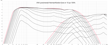
if you make the low frequencies gain by 10 dB (as in my case), then when increasing the volume the amplifier power limit in this area will quickly be reached and as a result clipping. A compressor or limiter is needed to limit the voltage in this area and as a result prevent clipping or damage to the amplifier. Look at the Harman graph, it is quite clear there
in my concept DSP will not be used. For now I would like to understand the principle itself, how to implement such a limitation as unnoticeably as in factory solutions
in my concept DSP will not be used. For now I would like to understand the principle itself, how to implement such a limitation as unnoticeably as in factory solutions
Maybe the issue is you don't need to boost but cut instead. 😉
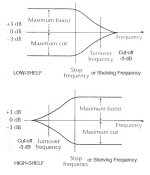
Let's consider the linked document: take a look at low shelf at maximum boost, then at high shelf at maximum attenuation: both profile are similar which means if you locate cutoff point for them to surimpose you'll have same response but the high shelf will need to be compensated in level ( up your volume knob to compensate for level loss).
It's way safer than implementing a boost and as you cut you won't have headroom issue as with a boost ( the situation you describe with your 10db boost clipping the amp).
As it'll be used for low listening level you won't need anything to 'protect' from misuse, imho. If someone bypass the cut, the woofer will not meet xlimit ( the treshold of destruction of displacement) and the sound will just seems to have less accentuated bass ( 10db is a lot, you'll feel it as 2x less bass).
The other issue is related to the way your woofer is loaded: bass reflex or sealed.
Bass reflex doesn't react well to eq ( you have to be careful especially with boost). Sealed might be easier.
As i already told multiband compression on dsp is what 'factory' use. And you probably don't hear them because they trigger only to protect the driver ( iow at vey high levels) not in normal use. The solution i gave is a kind of 'poor man' solution following same principle. It's not implemented by factory because it's not easy to sell to end users.
Attachments
Last edited:
I agree that it can be implemented as you write, based on the "loudness" principle. But I don't really know how to implement it without physical volume controls. I have a Bluetooth speaker, and all volume is controlled using my phone.
A simple switch on your amp: on/off. The circuit can be implemented upfront your amplifier ( before xover for it to be shared by both way in case it's needed by shelves curve).
As it will cut all mid and hf you'll certainly need to play a bit with levels when engaged/disengaged.
As it will cut all mid and hf you'll certainly need to play a bit with levels when engaged/disengaged.
The issue with 'loudness compensation' is it's not a fixed parameter: gain ( or attenuation) should follow the listening level as it is supposed to compensate our loss of sensibility in lows and high freq when level lowers and this is not constant. It is related to Fletcher- Muson curves.
A fixed gain will work for a fixed Spl.
It's always been an issue until dsp appeared.
A fixed gain will work for a fixed Spl.
It's always been an issue until dsp appeared.
I would like to eliminate the switches so that this process happens automatically, eliminating the human factor.Простой переключатель на вашем усилителе: вкл/выкл. Схема может быть реализована перед вашим усилителем (до кроссовера, чтобы она была общей для обеих сторон, если это необходимо для кривой полок).
Так как он обрезает все средние и высокие частоты, вам определенно придется немного поиграться с уровнями при включении/выключении.
Last edited:
You had an issue with translator. 😉
Apologize i don't speak or read Belarus language.
Apologize i don't speak or read Belarus language.
Last edited:
Well i suppose this could be implemented by software ( both eq profile + on/off) but i can't help.
Eliminating human factor? 'We are the Robots' as would had Kraftwerk said. 🙂
Idiot proof doesn't exist (sadly). Even dsp processed system are threatned by operators.
Maybe you'll have other answers to help.
Eliminating human factor? 'We are the Robots' as would had Kraftwerk said. 🙂
Idiot proof doesn't exist (sadly). Even dsp processed system are threatned by operators.
Maybe you'll have other answers to help.
If you want an analog solution, something in this thread might point you in a direction:
www.diyaudio.com/community/threads/conversion-from-level-dependent-to-level-independent-loudness-effect-what-rules.365053
As stated earlier, this is typically done in DSP now. Small, cheap DSP amplifiers are pretty common. SigmaStudio is one environment for this kind of work. Here's a thread related to adaptive loudness control in it:
https://ez.analog.com/dsp/sigmadsp/f/q-a/121790/adaptive-loudness
Хотелось бы разобраться в алгоритме обработки, это интереснее чем слепо повторять проекты с использованием DSP
@Pirotex2005
Discussing the concepts.
Looking at the curves you've posted (I never played with these boxes), it seams Harman implements a variable bass equalization level according to the signal level and not a compressor.
If signal is low, bass is amplified and if signal is high, frequency response becomes flat. That's the principle of loudness system.
In order to make it automatic and without any physical references to volume, so the eq doesn't know how the physical or digital volume is set, you have to build 3 blocks thinking about an analog circuit:
-An average or RMS signal detector so as to estimate the volume - the output is a voltage proportional to the volume
-Low pass filter for shelf filter or a girator for band pass filter
-VCA (Voltage Control Amplifier)
From input, the average signal detector will produce a voltage proportional to the signal volume.
This voltage is fed into the VCA, which in turns, control the amount of signal from low pass filter.
If VCA produces infinity attenuation, frequencey response is flat.
If VCA produces amplification, the frequency range filtered out in the low pass will add to the main signal increase bass response.
In the blocks below, you'll adjust the frequency range, how much boost, how fast/slow volume will be detected, which frequency range you will choose as reference for avg signal detector etc. Many options.
In DSP, the concept is similar, but things are easier and more efficient than done in analog opamps in real time.
I don't play with DSP's, I just play with opamps.
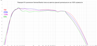
If we focus on the system's reaction to sharp signals, this is precisely a compressor/limiter. At first, there is a typical surge and a sharp decrease in amplitude to the required value. After the level drops below the threshold, recovery occurs. This is also indicated by the different response of the amplifier to a sweep of different duration. Note that the short and long have different frequency responses.Looking at the curves you've posted (I never played with these boxes), it seams Harman implements a variable bass equalization level according to the signal level and not a compressor.
In general, when examining amplifiers of different factory speakers, I noticed different concepts. In some cases, classic compression is visible, where a decrease in the signal level affects the volume of the entire range, and the second is where the process occurs as if separately. What is interesting is that in both cases, you can achieve good results , without pronounced artifacts such as pumping or breathing. But in the second case (JBL, Harman), it works most cleanly and naturally. The main thing I would like to understand is whether they use functions unique to digital devices such as look ahead, or whether they use classic techniques but with ultra-short attack and release time. If there is signal processing in advance due to a delay, then it will hardly be possible to implement something like this in an analog circuit in principle.
Attachments
I doubt they use typical compressor, i would look for dynamic-eq ( eq profile is driven by dynamic behavior). When i look at graph i clearly see the 'smiley' eq taking place, this a compressor can't do even multiband.
Look ahead is indeed something only digital can bo but it's not the only issue you'll face trying to implement a multiband compressor in analog: filtering is a real challenge ( the recombination in perticular as you do not want to mess up phase in the voice inteligibility range). This is the main reason there is so few analog multiband compressor on the market.
Ultra short attack and release does not make sense in low end: how long duration is a cycle at 100hz and lower? Adaptive release time is easy to implement in analog ( dual time constant sidechain, one with short release (let's say 50ms) another with something like 500ms is what is usually seen on 'transparent' sounding comp).
If you look at the jpeg in your zip file you have the attack time clearly visible but i repeat for me it's dynamic eq.
Last edited:
A solution would be to find yourself a good used ART Pro VLA2 stereo compressor and swap out the crispy sounding Chinese tubes. You can chose between FET and opto coupler based circuits. Noise is low, which makes it capable of being run in Iine with the final stage before amplification. You can also side chain an EQ to emphasize a specific low end band.
https://artproaudio.com/microphonepreamps/product/293543/provlaii
https://artproaudio.com/microphonepreamps/product/293543/provlaii
Last edited:
Ok, you can classify as a compressor since when level increases, some part of amplification decreases.If we focus on the system's reaction to sharp signals, this is precisely a compressor/limiter. At first, there is a typical surge and a sharp decrease in amplitude to the required value. After the level drops below the threshold, recovery occurs. This is also indicated by the different response of the amplifier to a sweep of different duration. Note that the short and long have different frequency responses.
In general, when examining amplifiers of different factory speakers, I noticed different concepts. In some cases, classic compression is visible, where a decrease in the signal level affects the volume of the entire range, and the second is where the process occurs as if separately. What is interesting is that in both cases, you can achieve good results , without pronounced artifacts such as pumping or breathing. But in the second case (JBL, Harman), it works most cleanly and naturally. The main thing I would like to understand is whether they use functions unique to digital devices such as look ahead, or whether they use classic techniques but with ultra-short attack and release time. If there is signal processing in advance due to a delay, then it will hardly be possible to implement something like this in an analog circuit in principle.
It doesn't change the analysis of the concepts, which was you first question.
The point here is this is done via multi-band treatment.
The typical artifacts pumping/breathing you've mentioned, occur when you treat the signal as a whole frequency range.
Buiding at least 2 bands, as I described, you'll not fell that since upper frequencies would never change due to the VCA influence.
But yes, there are lots of limitation in analog signal processing - world has shifted to digital.
With digital approach, you can achieve better results, as krivium mentioned - you can look ahead by operating the signal in the memory, so you know the "future" and can act with much more accuracy.
But, as I said, DSP is not my focus.
And mine too🙂But, as I said, DSP is not my focus.
My whole project is based on operational amplifiers
Keeping it analog, the circuit can only react from what happens in real time. It will never be perfect.
You have to tweak the attack, decay, release constant times to do the best that can be done.
Select proper frequency range for either average detector and band amplification/attenuation as well as the amount of bass boost.
Try more number of bands.
You mentioned optcouplers, I understand you are talking about photo resistor couplers, right?
This way you keep the VCA based on resistor and not in a semiconductor. I think the result will be better.
Or, if you can buy in your region, there are IC that implements VCA and you don't have to build it.
Search for "IC for VCA" - they are cheap, but not always easily available in all countries.
A lot of fun for those who like theses things, myself included.🙂
- Home
- Loudspeakers
- Multi-Way
- Compressor question