I gathered these few simple two transistor compound preamplifiers. Would like to know if anyone built some like it, how it worked, which are best performing.
Are there web pages dedicated in designing these Sziklai simple circuit with explaining what part does what?
I noticed some sport feedback cap from output, some don't.
Just want to learn some more. Plus i just optimized nice 3 tap loudness volume pot, which reduces signal to some degree, so instead of simple buffer, i could built simple nice pre.
Attachments

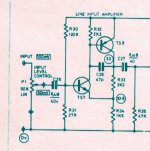


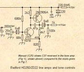
The one called 'Line Preamp' is from the Radford ZD control unit and is a text book implementation imo. It delivers really excellent performance, I have used these in the past.
Gain is (R33/R34)+1. R32 helps remove minority carriers from the base of the PNP transistor and greatly improves HF performance although the circuit will appear to work 'normally' without it. C26 tames the HF and phase response in a totally defined and controlled way.
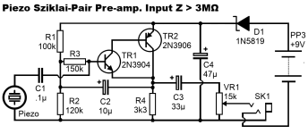
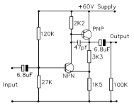
Your first image has a bootstrapped input stage (via C2) which allows the output voltage to modulate the bias voltage provided by R1 and R2. The effect of doing that means no voltage is developed across the 150k (and so the input impedance now appears as extremely high. Remove C2 and the input impedance is the 150k in series with the parallel value of R1 and R2. Voltage gain overall is '1' so a buffer.
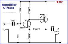
The others are all variations on the same themes but the Radford is the definitive one
Gain is (R33/R34)+1. R32 helps remove minority carriers from the base of the PNP transistor and greatly improves HF performance although the circuit will appear to work 'normally' without it. C26 tames the HF and phase response in a totally defined and controlled way.
Your first image has a bootstrapped input stage (via C2) which allows the output voltage to modulate the bias voltage provided by R1 and R2. The effect of doing that means no voltage is developed across the 150k (and so the input impedance now appears as extremely high. Remove C2 and the input impedance is the 150k in series with the parallel value of R1 and R2. Voltage gain overall is '1' so a buffer.
The others are all variations on the same themes but the Radford is the definitive one
As I recall, there was a complete Leach preamp project that used this topology. He probably explained the design as he did for the Leach Power Amp design published in "Audio" magazine in the 70s, too.
OK, found a link to the article, but did not reread it: https://leachlegacy.ece.gatech.edu/papers/wbpreamp/feb77article.pdf. I think he published a update later in 1977 for the power supply.
OK, found a link to the article, but did not reread it: https://leachlegacy.ece.gatech.edu/papers/wbpreamp/feb77article.pdf. I think he published a update later in 1977 for the power supply.
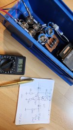
Since the storm is approaching and no outdoors activity is planed, i started gathering parts for radford pre.
Got plenty of bc550/560.
Could use bc550 in the front.
Is it my understanding that radford front and output bjt do not have to be complementary?
Because i got plenty of a1145 and c2705. Complementary pair of small signal bjt used in yamaha pre. Can handle more current.
Could use a1145 on output.
Got plenty of bc550/560.
Could use bc550 in the front.
Is it my understanding that radford front and output bjt do not have to be complementary?
Because i got plenty of a1145 and c2705. Complementary pair of small signal bjt used in yamaha pre. Can handle more current.
Could use a1145 on output.
Last edited:
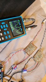
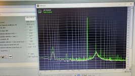
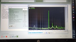
Some progress. It works from the start. Powered by ~59VDC, with sine output ~960mVpkpk, 327mVrms, it has distortion 0.063%, likely better since my supply is not the best at the moment.
Attachments

Last edited:
er "...sine output ~960Vpkpk." I think this value is mV 😉Some progress. It works from the start. Powered by ~59VDC, with sine output ~960Vpkpk, 327mVrms, it has distortion 0.063%, likely better since my supply is not the best at the moment.
Yes, was able to edit in time. You can clearly see reading on the scope.er "...sine output ~960Vpkpk." I think this value is mV 😉
Basically correct in this design. But if you've got them yet, why not use them?Is it my understanding that radford front and output bjt do not have to be complementary?
Best regards!
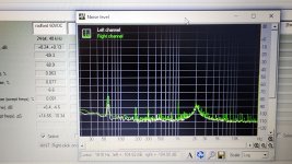
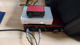
Swapped nuforce dac with shiit, things got much cleaner.
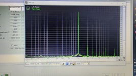
My loop is now -130dB noise floor with some hum at -100dB, and distortion is only 0.0015%.
Well, i got one better dac, but its being used now.
I remeasured radford, got the same results, ~0.05% distortion, equal amount of 2nd and 3rd harmonic. Looking forward to some listening sessions.
My loop is now -130dB noise floor with some hum at -100dB, and distortion is only 0.0015%.
Well, i got one better dac, but its being used now.
I remeasured radford, got the same results, ~0.05% distortion, equal amount of 2nd and 3rd harmonic. Looking forward to some listening sessions.
Attachments
I looked into a circuit like this, but with current source biasing, when I made a preamplifier halfway the 1990's. In the case of a voltage follower with bootstrapping, you usually get a trough in the input-impedance-versus-frequency curve and possibly a peak in the transfer from input to output.
For example, suppose TR1 and TR2 of this circuit were an ideal voltage follower:

To make the equations simpler, I define that R12 is the parallel value of R1 and R2.
Network analysis shows that the input impedance of everything to the right of C1 is then equivalent to the series connection of an inductance L = C2 R3 R12 and a resistance R = R3 + R12. At the resonant frequency of L with C1, the input impedance of the whole circuit has a minimum equal to R, the input impedance you would have had without bootstrapping. (You can, of course, put this resonant frequency at some deep subsonic frequency.)
When the quality factor of the equivalent LRC circuit is greater than (1/2) √2 and the circuit is driven from a low-impedance source, the complex poles lead to peaking. The quality factor is
Q = √(L/C1)/R
On top of that, you get peaking due to the zero formed by L and R, but you can correct for that with a first-order high-pass filter (AC coupling) elsewhere. For example, by making
C3 VR1 = L/R.
Edit: you can see my version in the bottom left corner of the hand-drawn schematic of this post: https://www.diyaudio.com/community/threads/tone-and-loudness-controls.405853/post-7567174 The 1 Mohm resistor is deliberately not bootstrapped to make the impedance minimum less deep (shunt rather than series damping of the equivalent LC circuit).
For example, suppose TR1 and TR2 of this circuit were an ideal voltage follower:
To make the equations simpler, I define that R12 is the parallel value of R1 and R2.
Network analysis shows that the input impedance of everything to the right of C1 is then equivalent to the series connection of an inductance L = C2 R3 R12 and a resistance R = R3 + R12. At the resonant frequency of L with C1, the input impedance of the whole circuit has a minimum equal to R, the input impedance you would have had without bootstrapping. (You can, of course, put this resonant frequency at some deep subsonic frequency.)
When the quality factor of the equivalent LRC circuit is greater than (1/2) √2 and the circuit is driven from a low-impedance source, the complex poles lead to peaking. The quality factor is
Q = √(L/C1)/R
On top of that, you get peaking due to the zero formed by L and R, but you can correct for that with a first-order high-pass filter (AC coupling) elsewhere. For example, by making
C3 VR1 = L/R.
Edit: you can see my version in the bottom left corner of the hand-drawn schematic of this post: https://www.diyaudio.com/community/threads/tone-and-loudness-controls.405853/post-7567174 The 1 Mohm resistor is deliberately not bootstrapped to make the impedance minimum less deep (shunt rather than series damping of the equivalent LC circuit).
Last edited:
I have been involved in loudness contour lately. Do not want to repeat myself from what i already said in another thread, loudness volume control, as part of volume makes no sense, since people can use different efficiency speakers, thus same contour would be applied to different spl. But loudness pot volume independent is completely personal feature and can be quite useful.
So i made yamaha louness contour. Optimized the values to suit my needs. Waiting for dual linear 10k pot to put it in the box. It will be totally passive and separate. Could be used between mp3 player and headphone amplifier. To make ultimate headphone listening experience.
Then i optimized 3 tap lodness pot to my liking, not to be used just as volume pot, but as ultimate loudness. One would simply select level of loudness contour using 3 tap pot, then followed by buffer or great sounding simple pre...(like this radford, hint, hint) then headphone amp. With its volume pot.
I already asked that question in Hamptone thread...why some circuits have two identical pre in series? Like Goldmund, Hamptone, or others? Why not to put lodness contour in one section, and normal volume control then? Or other way around, possibilities are limitless.
Just some ramblings...
Yup. I finished the pre into nice case from former commercial tube pre, which sucked, but i was using it as active crossover only.Excellent. I think you will find them sonically excellent.
Even i had only ~40 Vdc available (+/-20Vdc), it sounds amazing. Once i got rid of the buzz, i listened briefly in upstairs test system, betsy open baffle with b&g open back tweeter, with small jlh classA amp. Adding radford pre made system more enjoyable. So i moved radford downstairs in the kitchen. It replaced jfet buffered volume control. Even gain is not needed, classical music sounds better now, fuller, i like it. Bach harpsichoid is much sparklier than just the buffer.
Yup, this is simple yet great pre.
Cheers.
- Home
- Source & Line
- Analog Line Level
- Compound (Sziklai) pre