I would like to share the method to compose an i2s audio data stream in this post.
We can then use it to verify the audio data just before entering the DAC is real bit perfect by oscilloscope
There are many situation the audio data send to the DAC is not what it expect.
Many people may not know use volume control in the OS mixer with all usb to i2s convertor will ruin the bit perfect audio data. To avoid this problem, specific firmware for each DAC is needed to set the DAC volume register for volume control.
There are many way including the sound driver can also ruin the bit perfect audio data stream, user can do a quick test after reading this post, it's fun and easy.
Example: when using the windows direct sound driver, playback 16bit audio data, in full volume we should expect it is bit perfect, but you will see 17bit is sending to the DAC in the oscilloscope! The leading 15bit is bit perfect, but there are 2bit added in mystery. Newer version of driver may have correct this problem.
Let's come back to the main topic of this post.
Using oscilloscope to verify normal audio data in the i2s bus is hard normally, as the audio data is continuous changing.
We can not read a stable image in the oscilloscope.
The only way is compose an i2s stream which it can be shown stably on the oscilloscope.
I choose the WAVE format, it is raw and it is also my beginning of computer music since 30years ago.
There are two way to compose an i2s audio data stream in WAV file.
Read the microsoft wave format specification and write from the first byte.

https://msdn.microsoft.com/en-us/library/windows/hardware/ff536383(v=vs.85).aspx
It's time consuming and hard for most people.
I use a much faster and simple method, edit a normal audio data wave file, it should be done easily by most people
We start from the basic, 16bit:
Step 1: sox is a great and free program to generate wave flie, we uses it to generate a 16bit wave file.
Step 2: To distinguish the left and right channel data in the oscilloscope, 1010101010101010 for the left chanel and 1010110011001010 for the right channel.
Step 3: replace the left and right channel audio data in the wave file with the above binary. and that's done.
It's really a fun to verify the combination of your hardware device and software driver if it is real bit perfect.
You can also run the verificatoin for few hour while you are using the computer for the other work,
Most oscilloscope have the function to catch different over a period of time and count.
Some usb to i2s convertor may send bad i2s data while the computer is in heavy usage.
I use this method to test my new implementation on the famous Analog Device AN207 stop clock convertor board.
It help me to perfectly tune the signal timing and eliminated the bug easily and faster.
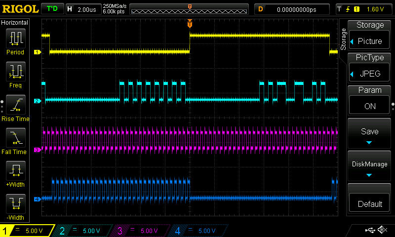
The below image is the output my AN207 convertor board prototype.
Yellow: LATCH for left and right DAC
Cyan: DATA for left and right DAC
Purple: Right clock
Blue: Left clock
Warning: Disconnect the DAC output before sending your test i2s stream. I have no idea what the 1010101010101010 and 1010110011001010 will sound from the DAC, it may contains dc offset and it can damage your speaker seriously.
Any comments or improvement on the above method is welcome. If you think it's useful, please give me a thumb^^
We can then use it to verify the audio data just before entering the DAC is real bit perfect by oscilloscope
There are many situation the audio data send to the DAC is not what it expect.
Many people may not know use volume control in the OS mixer with all usb to i2s convertor will ruin the bit perfect audio data. To avoid this problem, specific firmware for each DAC is needed to set the DAC volume register for volume control.
There are many way including the sound driver can also ruin the bit perfect audio data stream, user can do a quick test after reading this post, it's fun and easy.
Example: when using the windows direct sound driver, playback 16bit audio data, in full volume we should expect it is bit perfect, but you will see 17bit is sending to the DAC in the oscilloscope! The leading 15bit is bit perfect, but there are 2bit added in mystery. Newer version of driver may have correct this problem.
Let's come back to the main topic of this post.
Using oscilloscope to verify normal audio data in the i2s bus is hard normally, as the audio data is continuous changing.
We can not read a stable image in the oscilloscope.
The only way is compose an i2s stream which it can be shown stably on the oscilloscope.
I choose the WAVE format, it is raw and it is also my beginning of computer music since 30years ago.
There are two way to compose an i2s audio data stream in WAV file.
Read the microsoft wave format specification and write from the first byte.
https://msdn.microsoft.com/en-us/library/windows/hardware/ff536383(v=vs.85).aspx
It's time consuming and hard for most people.
I use a much faster and simple method, edit a normal audio data wave file, it should be done easily by most people
We start from the basic, 16bit:
Step 1: sox is a great and free program to generate wave flie, we uses it to generate a 16bit wave file.
Step 2: To distinguish the left and right channel data in the oscilloscope, 1010101010101010 for the left chanel and 1010110011001010 for the right channel.
Step 3: replace the left and right channel audio data in the wave file with the above binary. and that's done.
It's really a fun to verify the combination of your hardware device and software driver if it is real bit perfect.
You can also run the verificatoin for few hour while you are using the computer for the other work,
Most oscilloscope have the function to catch different over a period of time and count.
Some usb to i2s convertor may send bad i2s data while the computer is in heavy usage.
I use this method to test my new implementation on the famous Analog Device AN207 stop clock convertor board.
It help me to perfectly tune the signal timing and eliminated the bug easily and faster.
The below image is the output my AN207 convertor board prototype.
Yellow: LATCH for left and right DAC
Cyan: DATA for left and right DAC
Purple: Right clock
Blue: Left clock
Warning: Disconnect the DAC output before sending your test i2s stream. I have no idea what the 1010101010101010 and 1010110011001010 will sound from the DAC, it may contains dc offset and it can damage your speaker seriously.
Any comments or improvement on the above method is welcome. If you think it's useful, please give me a thumb^^

- Status
- Not open for further replies.