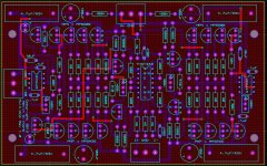
I've just added a picture of the clone PCB. I've got a separate thread open which helped identify some of the unknown components. No-one has been able to come up with a schematic.
If you have the other side of the pcb, I can reverse-engineer the schematic for you.
But wait, I've seen such a board recently with this 14-pin dil double npn-pnp ic on this forum somewhere!
But wait, I've seen such a board recently with this 14-pin dil double npn-pnp ic on this forum somewhere!
The alternative is a classic DRV134 board.
DRV134 Unbalanced To Balanced Dual Channel Converter Board DC 5-24V Single Power | eBay
DRV134 Unbalanced To Balanced Dual Channel Converter Board DC 5-24V Single Power | eBay
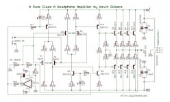
I've seen that schematic before, it is KGs headphone amplifier. it uses dual JFET LTP. This board uses transistors in a DIL package, the THAT340P.
I don't have the PCB yet, it's coming from China.
I don't have the PCB yet, it's coming from China.
Last edited:
What I see is that the front stage is comparable, but the output stages are adapted to their use, a symaym2sym or hp amp.
If it disappoints however, I'll send you a simple stable 12Q-18R-2C symasym2sym circuit draft I've developed recently. Any ps is good, no adjustments, only 4 good ≤1%resistors needed, rest is indifferent.
If it disappoints however, I'll send you a simple stable 12Q-18R-2C symasym2sym circuit draft I've developed recently. Any ps is good, no adjustments, only 4 good ≤1%resistors needed, rest is indifferent.
12 transistors (denoted as Q#), 18 resistors (ditto R#), 2 capacitors (''C#), all to the bare needed minimum. Shortings on the compatitive league are my grounds <-> shortings on the compatitive grounds are my league. {Is this or which of this is english language proper?}
It doesn't need a huge bridge rectifier as it only draws about 250mA.
I don't like the bridge glued on top of the trafo.
I don't like the bridge glued on top of the trafo.
I've used that method for years in low current circuits.
- Home
- Amplifiers
- Solid State
- Componment placement