I have searched but cant find a specific answer to this, should be pretty simple though!
I would like to build a simple op-amp buffer circuit to go in between a volume pot and the input to a chip amp (eg LM3875 Circuit Below).
I cant work out if I need:
1. An output/input cap in series between the op amp and the power amp.
2. A load resistor for the op-amp before this cap and possibly an input resistor after this cap for the power-amp.
3. A series resistor before or after the cap.
4. Inverting or Non-Inverting circuits for simplicity.
You can probably tell I'm having problems grasping what these components do, my concern is that if they form RC filter circuits I need to make sure I don't mess with the cut-off frequencies.
Thanks
Attachments

Hi,
you are showing a DC coupled power amp.
It has 680r//22k on the inverting input.
You require approximately the same loading on the non-inverting input to minimise the output offset.
You already have 220r at the input, you need another 460r.
You have a choice, either increase the 220r to 680r or add the extra resistance at the output of the buffer. The volume control and the buffer can be located at any convenient position. The cables driven by the buffer can be any length to reach remote power amps.
Now to your filters.
I recommend filtering both the buffer input and the power amp input.
Try 0.5uS to 1.5uS at the power amp. Many find using the higher end of that range cuts too treble but it suits some combinations of speakers/rooms/ears.
Try 0.1uS to 0.5uS at the buffer input.
Now consider what happens if the buffer or the source sends a DC signal to the power amp.
I recommend a DC detect circuit that activates a speaker protection relay.
Finally the RC time constants quoted above can be used to find your R & C values for the passive 6dB/octave filters.
1.5uS=0.0000015S. This can be made from a 1k0 resistor and a 1.5nF capacitor (1k0 * 1.5nF = 1000 * 0.0000000015 = 0.0000015).
Any other combination of R & C can be used that R*C=time constant required. eg 680r & 1nF = 0.68uS
Thanks for that information.
Looking at the input and using an online calculator I get about 7hz cutoff using a 1uf input cap on the power amp. This sounds like a good starting point.
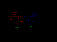
If I were to join the 2 circuits together as in the (fairly poor) diagram below would I just need one cap , one series resistor and one resistor to ground instead of 2 of everything? (As long as the RC frequencies are ok)
Looking at the input and using an online calculator I get about 7hz cutoff using a 1uf input cap on the power amp. This sounds like a good starting point.
If I were to join the 2 circuits together as in the (fairly poor) diagram below would I just need one cap , one series resistor and one resistor to ground instead of 2 of everything? (As long as the RC frequencies are ok)
Attachments
Hi,
you have shown a DC coupled amplifier in the first post and are showing a DC blocking capacitor in post3. This is a high pass filter.
This DC blocking cap converts the input to AC coupled but leaves the NFB without a DC blocking cap.
Which do you want? DC coupled or AC coupled or mixed AC & DC coupling?
The filters in post2 are all low pass for interference suppression..
Your diagrams omit these completely!
BTW,
many recommend the power amp high pass filter, if fitted, to be below 4Hz and I recommend below 2Hz.
The buffer HP input filter, if fitted, is usually set to an even lower frequency.
I clearly need to learn more about this! I've built amps in the past and not worried about things like this, just built a pre amp circuit from one schematic, a power amp from another and just connected the output of one to the input of the other. Ignorance is bliss.
I added the cap to the power amp input as I thought that was what you meant by:
"I recommend filtering both the buffer input and the power amp input.
Try 0.5uS to 1.5uS at the power amp."
Re reading your post I see that the filter you recommend is to filter out frequencies above about 100khz so would need an input cap going to earth not in series.
I think I will do some more research before asking any more questions, thanks for your help.
- Status
- Not open for further replies.