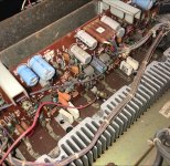
Partially assembled.
Just found out that my rectifier board and power supply board are different from the service schematics that I have, so be careful when you are restoring your set.
I decided to do away with speaker A and B selection switching altogether.
So the output from the power amp board goes to the relay and out to the speaker posts behind.
Love the way they designed the chassis, so serviceable!

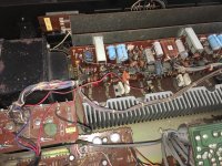
That transformer is letting the side down, needs a good clean and polish to match the chassis now 😉Partially assembled.
Just found out that my rectifier board and power supply board are different from the service schematics that I have, so be careful when you are restoring your set.
I decided to do away with speaker A and B selection switching altogether.
So the output from the power amp board goes to the relay and out to the speaker posts behind.
Love the way they designed the chassis, so serviceable!
I replaced the wire grip terminals on the speaker outputs with some decent quality 4mm sockets. There is a guy on eBay that can sell you the correctly sized acrylic with fixings or complete with sockets. I just bought the acrylic and used better quality sockets. If you search for TA-5650 on eBay, you will find him. Just send a message for the acrylic only.
D
Also, Andy swapped all signal path Electrolytics fro foil caps ( all 10uF 100v) and I copied him. It does make a difference.
Also ensure you are referencing the most up to date Service Manual, the colour one on HFE is older than the lower quality one, so check both and use the component values from the more modern one.
The Dutch SM also has some component value substitution and different bias setting that need to be applied.
Finally, did you do all the diode mods and split supply balance mod?
Jon
Did you replace the trim pots with multi-turn 2.2k ones? (It looks like you have).Partially assembled.
Just found out that my rectifier board and power supply board are different from the service schematics that I have, so be careful when you are restoring your set.
I decided to do away with speaker A and B selection switching altogether.
So the output from the power amp board goes to the relay and out to the speaker posts behind.
Love the way they designed the chassis, so serviceable!
Also, Andy swapped all signal path Electrolytics fro foil caps ( all 10uF 100v) and I copied him. It does make a difference.
Also ensure you are referencing the most up to date Service Manual, the colour one on HFE is older than the lower quality one, so check both and use the component values from the more modern one.
The Dutch SM also has some component value substitution and different bias setting that need to be applied.
Finally, did you do all the diode mods and split supply balance mod?
Jon
I used a 2kohms multi-turn pot from my stash, did the death diodes mod, and the split supply double diodes too. My set came with all the updated resistors as per the service bulletin, so I just bias it @50mV.
I will try those film caps for signal path later on, as most components are out of stock from Mouser. I intend to use a 15000uf replacement for the main caps when stocks are available.
It is singing now, but I had some hums issues from the preamp section, I removed the pre-power jumper and connect it to my Yarra Preamp, the TA-5650 power amp works perfectly without and hums from the speakers.
Is the preamp section worth looking into? I am not a fan of the signal path going thru multiple switches and tonal control in between.
That's good advice, cross reference the two though, because the 'correct' later manuals are such lousy quality. Most of the board is the same though, and you'll have spotted the wrong orientation of some polarised caps on the silkscreenAlso ensure you are referencing the most up to date Service Manual, the colour one on HFE is older than the lower quality one, so check both and use the component values from the more modern one.
Haven't found a SM with 2SK79's identified in the pre-amp section. As I have found out you need to keep your wits about you!
Looking good, did you change the PSU caps? for what, if you did?
Andy
Lead times are frustrating at the moment. I bought the last few of those film caps from Digikey I think. (I also insulated the long leg with a bit of the tube from the IPA spray can to prevent short circuits)I will try those film caps for signal path later on, as most components are out of stock from Mouser. I intend to use a 15000uf replacement for the main caps when stocks are available.
For phono it's supposed to be highly recommended because of the baby Vfets but its very "of its time" . It's very switchy but most of it is switched out. i guess it depends on how you feel about that buttons that don't do anything.Is the preamp section worth looking into? I am not a fan of the signal path going thru multiple switches and tonal control in between.
Andy
I have used these for my TA-4650, they are 10000uf upgraded from the stock 4700uf
647-LNT1J103MSE
647-LNT1J103MSE
And we're off - TA-5650 is up and running without any short circuits or anything 🙂
Observations,
Andy
Observations,
- Rank 53 VFets are usable (relief)
- Bias does take a while to come up with them it's only around 2-3mV by the time the relay switches
- Bias wanders (at least it does here) +/- 7mV seems like the sort of range
- I have three smaller knobs on this one for the Bass, Treble and Balance. Is that a feature? All other sets are the same
- The bulb PL1 is working in the power switch but the power resistor (R420 - 2W 820R) is hot as in 80C+ Since PL1 is a 4.5v 40mA unit and is being fed with that, I guess that's normal 😱
Andy
Especially interesting as I wondered about upping the caps on mine and ultimately chickened out - After buying a pair of 6800uFI have used these for my TA-4650, they are 10000uf upgraded from the stock 4700uf
647-LNT1J103MSE
Andy
I used 10000uF in my 4650, Kemet ones I believe, but would need to check. Likely to replace the main filter caps in the 5650 as they are now 40+ years old.
If you want to use the Loudness function then will need the preamp in circuit. It is decent enough.
If you want to use the Loudness function then will need the preamp in circuit. It is decent enough.
Did you bias it with the lid on? I noted that the pre-amp board is pretty sensitive to noise with the lid off, with lid on it is pretty quiet. Also need to have steady temp. My bias was pretty steady once set, the 4650 was more dynamic in the bias, but steady with lid on.And we're off - TA-5650 is up and running without any short circuits or anything 🙂
Observations,
I should be happy this is up and running but frankly I'm more glad its over Mr Frodo
- Rank 53 VFets are usable (relief)
- Bias does take a while to come up with them it's only around 2-3mV by the time the relay switches
- Bias wanders (at least it does here) +/- 7mV seems like the sort of range
- I have three smaller knobs on this one for the Bass, Treble and Balance. Is that a feature? All other sets are the same
- The bulb PL1 is working in the power switch but the power resistor (R420 - 2W 820R) is hot as in 80C+ Since PL1 is a 4.5v 40mA unit and is being fed with that, I guess that's normal 😱
Andy
My knobs are all the same size apart from the volume.
Last edited:
The lot on? I did the set up with the rear chimney installed. - made no difference to when it wasn'tDid you bias it with the lot on?
Agree steady temp is a must and I have seen variations in bias just from blowing on the HS before now. (esp, on the 4650)
IIRC there is a note somewhere about waiting 3 minutes or something before setting bias too. I just watch each channel as it rises and wait, and wait, and wait...
I'm setting 45mV BTW. So a long way below the original 90mV rating. Its also worth noting that the Fluke 115 meter I'm using wanders a bit on the mV scale anyway. It's a hand held, not a bench type. FWIW I also found a 'high' reading would stabilise if i changed channel (left to right) as the meter sorted itself out, so I'm going for it.
Were you using the Phono amp with the lid off? I've had no pre-amp related issues at all (yet)
Andy
Yeah, lid, I meant lid, have corrected it now, so will cause even more confusion in the future when folks read this thread.
I found that even with the input grounded, if I put my hand anywhere near the pre-amp board when lid was off, it would inject a load of noise into the amp and this would stuff the bias reading.
My 5650 is set to 50mV and the 4650 at 45mV, but they move around a little from there.
I found that even with the input grounded, if I put my hand anywhere near the pre-amp board when lid was off, it would inject a load of noise into the amp and this would stuff the bias reading.
My 5650 is set to 50mV and the 4650 at 45mV, but they move around a little from there.
Now that is an interesting mod.
Wonder if its an original 'we will keep these things alive' mod or just someones bright idea at a service? It's dusty enough to be in period but then whats the difference between 1980s dust and 2000's dust?
I THINK (and I am no expert) it mitigates any failure of the -44v rail when things are going south?
Andy
The original function was to open the output relay to disconnect the speakers and thus provide indication of overheating. If you can trace the circuit it may help determine its new function.
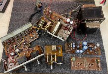
BITS
Does anyone (still) following this thread need any bits from a dead, filthy amp to complete or finesse a build?
Not sure this is the way to do it, but I need to clear some stuff from the Lab (or dining area as it's more usually known) These parts are never going to work again without the requisite Vfets so landfill beckons.
Keeping some of the bits including the 2SK79 VFET's for another project, but beyond that send me a message? If you need a spare foot, or some of the IO boards etc it's worth the ask. Might be good for fixing a scratchy pot or bad selector.
First come first served and if it's 2023 you're probably too late 🙂 because "reasons"
Andy
Attachments
Hi Andy,BITS
Does anyone (still) following this thread need any bits from a dead, filthy amp to complete or finesse a build?
Not sure this is the way to do it, but I need to clear some stuff from the Lab (or dining area as it's more usually known) These parts are never going to work again without the requisite Vfets so landfill beckons.
Keeping some of the bits including the 2SK79 VFET's for another project, but beyond that send me a message? If you need a spare foot, or some of the IO boards etc it's worth the ask. Might be good for fixing a scratchy pot or bad selector.
First come first served and if it's 2023 you're probably too late 🙂 because "reasons"
Andy
I could do with a spare foot and possibly an on/off switch too. If you have a spare amp board, or at least the driver transistors, these would be appreciated.
The filter cap board and power regulator board would also be useful as spares.
J
- Home
- Amplifiers
- Solid State
- Complimentary ramblings AKA another Sony TA-5650 V-Fet thread