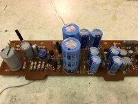
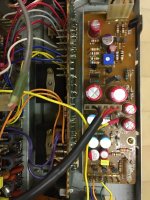
SOoo. then the power board of A TA5650
A little heap of evil genius in the original format - It has charge pumps / voltage doublers whatever you want to curse them by
Again i'm sticking to the principle of not changing values of capacitors, aware that the amp needs to wake in a specific order and that I'm not educated enough to know the full effects of changes. I have a suspicion that an actual electrical engineer might allow bigger caps to improve the charge pump - I am not that guy 🙂
Some, before's then
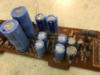
Attachments

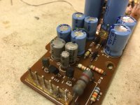
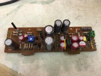
This is a weird hybrid write up I was all good with original board until fitting a new Q404 and after about the dozenth heat cycle the PCB did what was expected and quit. (AKA the pad came loose). Repaired it'll be 100% fine with new transistors... Cough "Yes, but actually no" is a popular meme that works here so now I'm calling that the test PCB
So first of all gut the board, I got carried away with the transistors before photos, new ones fitted at a Jaunty angle! EBC vs ECB actually works out. I tested this briefly in the test board 😉 and yes good. Voltages are where where they should be. (no vfets yet)
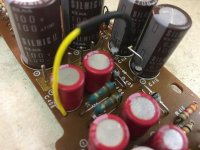
Diodes replaced (OK/not OK?) with BYV95C, fast soft recovery 600v capable types - comments please if you're a diode expert, I am not 🙁
Next is the voltage doubler mod:
https://www.diyaudio.com/community/threads/sony-ta-5650-voltage-doubler-mod.298656/
Note there is a big fat test point to drill into for the earth reference, but I'm getting ahead of myself, I haven't fitted it ahead of the capacitors because it'll get in the way. But my diode assembly methodology is in the photo's
So attached are the empty(ish) board and the test one for reference the test one with the new transistors in - Jaunty!
Hope that makes sense, if not the final board ought to make it clear. And now we wait for parts
Andy
So first of all gut the board, I got carried away with the transistors before photos, new ones fitted at a Jaunty angle! EBC vs ECB actually works out. I tested this briefly in the test board 😉 and yes good. Voltages are where where they should be. (no vfets yet)
Diodes replaced (OK/not OK?) with BYV95C, fast soft recovery 600v capable types - comments please if you're a diode expert, I am not 🙁
Next is the voltage doubler mod:
https://www.diyaudio.com/community/threads/sony-ta-5650-voltage-doubler-mod.298656/
Note there is a big fat test point to drill into for the earth reference, but I'm getting ahead of myself, I haven't fitted it ahead of the capacitors because it'll get in the way. But my diode assembly methodology is in the photo's
So attached are the empty(ish) board and the test one for reference the test one with the new transistors in - Jaunty!
Hope that makes sense, if not the final board ought to make it clear. And now we wait for parts
Andy
Attachments
Nice restoration work Andy!
I love the Vfet sounding of my TA-4650, that i am very tempted to gut out the power amp section and put it into a new chassis, making it solely a power amp unit. Hope to optimise further by removing all the input selector options as well as the output speakers selector switch function.
So it will be just simply, RCA input ---> power amp board---> SSR protection---> output to speakers.
Will this sounds any better?
Thanks,Nice restoration work Andy!
I love the Vfet sounding of my TA-4650, that i am very tempted to gut out the power amp section and put it into a new chassis, making it solely a power amp unit. Hope to optimise further by removing all the input selector options as well as the output speakers selector switch function.
So it will be just simply, RCA input ---> power amp board---> SSR protection---> output to speakers.
Will this sounds any better?
I don't know if it'll sound better, but you'd get the opportunity to at last use a more modern pre-amp. IMO the switching on the Sony amps is tremendously mechanical, I'm a mechanical engineer, and I don't like it! Lots of grubby contacts in the signal path. Plus capacitors etc. But on the other hand; it is all physically disconnected when you remove the pre-power jumpers. Have you tried using a different pre-amp? If so, what?
Then I stumbled across the original 2017(?) Vfet kit in the Diy-audio store. I can tell you that the boards are beautiful, but that's as far as I've got 🙂 worth a look if that is by some chance news to you. you can apparently use the same SK60/SJ18's
Now what would really be ideal is a mono board, based perhaps on the 4650 (or better 5650), without the 12 output devices needed by a TA-N8550!.
That's my 2cents anyway
Andy
More from what's becoming the project that won't die.die.DIE (hats off if you get that reference.)
Caps arrived (courtesy of Digikey this time) because, blow it; I wanted Elna - a perfectly sensible methodology for choosing components no? Well unless there is a poly equivalent 🙂
or film for that 0.47uf electrolytic
I've also swapped out the 6 pin header for a four and a two. The four will be wire wrapped as usual but the power bulb is not getting soldered (yay!) bootlace ferrules anyone??
Also another one to be mindful when getting that pretty service manual from Hi-FiEngine... More component changes here too! stick to the potato quality ones for the latest (after UK serial 600,351)
Anyway whats stopping proceedings? a dearth of 220 ohm resistors LITERALLY the only value missing in my stock and a big 2w thing is just silly 😀
Two resistors away from mayhem and 3 days before work... not sure I like those odds
Andy
Attachments
Last edited:
I posted those a while ago here ==> V-FET / SIT data sheets...in fact whilst I have the begging bowl out, if there's a decent 2SK60/2SJ18 datasheet then, yes that too 🙂
Cheers!
Cheers indeed - EPIC 🙂
So a bit of an update on the TA5650
New power board installed +20 and 97V line all good measured from their actual test points on the equalizer board
actually expecting to put this to bed today - everything is set
BUT there's a but 😡
Amp board voltages are off and I can smell warmth 'somewhere although haven't found a hot component yet
This isn't the by now normal "bias is wonky without vfets", I don't think. The +ve side comes up as expected, -ve side sits at -65v
So what have I found :
measured on the amp board relative to chassis gnd
+44v
+76v (AKA 94v)
-44v
are all good
-76 (AKA -94v) has a moment at start up of being 'correct', before slumping to -65v
There are two 330 ohm resistors in the supply path for the 'big volts' on the PSU board - R414 and R419, sure enough theres a 16.3v (IIRC) drop across the latter in the -ve supply side
I can disconnect the filter board with no change to the above.
To quote Sully, "Any Ideas?"
DANGER POST 🙂
Dear internet, I've been having thoughts, something that is always a risk.... On the VFet amps the supposed cause of death is usually that the bias disappeared somehow resulting in full flow through the VFet
Soooo how come simply adding a diode between the source and gate isn't a 'must do'
This surely is a silly idea because it would (in my head) protect VFets, We'd have heard about it
Just kicking it around. Because connectors are going to become a thing in the short term.
As for the problem at hand
Voltages across R342, R332, R392 and R382 are all 64V so I guess somethings at ground that shouldn't be, those are the first resistors the -94v supply sees when it gets to the power amp board.
Gonna play with the TAN-5550 while my brain works that out
Andy
Voltages across R342, R332, R392 and R382 are all 64V so I guess somethings at ground that shouldn't be, those are the first resistors the -94v supply sees when it gets to the power amp board.
Gonna play with the TAN-5550 while my brain works that out
Andy
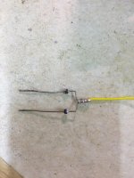
Give some of the capacitors a shuggle (with a wood chopstick) and see if the voltages jump around. I also had significant issues with probe contact on the T-03 connector board contacts, o could not get valid readings.
Hi Jon,
I actually used a rubber gloved finger trying to find any warmth, no change, its annoyingly stable - just wrong.... I've also had issues with those little vfet connector boards: hard to clean. hard to check. and must be more prone to failure than you'd like?
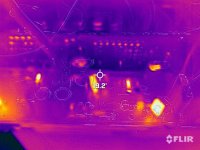
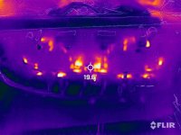
But more tech follows with infra red trickery, So as expected, power transistors are getting hot (duh) but I think its the resistors that tell a story, need to decouple the boards, wire wrapping or not... On the left we have R419 on the B-side much warmer than its bro' (R414) on the b+side
The very glowy object on the far left is the big 2 watt resistor so bright like a diamond that one. "bright" being say 30C so not much
For the moment I cannot discern what the 'hot' resistor is to the right: R406, R407, R408 one of those probably, but its odd to stand out
the FLIR is not mine, I've borrowed it from work, and hoping for more of a smoking gun TBH :/
Andy
I actually used a rubber gloved finger trying to find any warmth, no change, its annoyingly stable - just wrong.... I've also had issues with those little vfet connector boards: hard to clean. hard to check. and must be more prone to failure than you'd like?
But more tech follows with infra red trickery, So as expected, power transistors are getting hot (duh) but I think its the resistors that tell a story, need to decouple the boards, wire wrapping or not... On the left we have R419 on the B-side much warmer than its bro' (R414) on the b+side
The very glowy object on the far left is the big 2 watt resistor so bright like a diamond that one. "bright" being say 30C so not much
For the moment I cannot discern what the 'hot' resistor is to the right: R406, R407, R408 one of those probably, but its odd to stand out
the FLIR is not mine, I've borrowed it from work, and hoping for more of a smoking gun TBH :/
Andy
Attachments
So pretty bummed out here - I might have really messed this one up I think, or at least something has gone awry while I was at it.
This was supposedly a finished project mid January 🤐
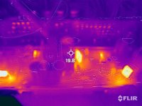
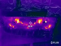
Today I disconnected the power amp board and actually voltages from the PSU board are good. Including +20v and the 'ninetysomething' on the EQ board
R402 is still a bit warm according to FLIR but R419 and R414 are now equalised
So guess a fault somewhere on the power amp board, With the negative side drawing too much juice? I'll be the first to admit that my lack of education, especially on the solid state side really hurts when it comes to fault finding. I'm no more than a monkey with a meter...
I mean I tried reading "Self on audio" but.. IMO - could put a corpse to sleep (If Mr Self should spot this #1 cheap shot apologies! #2 Morgan Jones)
Anyway I digress - due to not actually knowing whats next, Sony's wire wrapping is not helping as you can't connect / disconnect anything without penalties
I 'may' have mentioned previously I "DO NOT LIKE" wire wrapping...
IR photo shows the two pass transistors doing their job and that sneaky R402 above ambient - need too look at that next. This is all sub 30C by the way if I stick my thumb in, you wouldn't see anything except that.
However, without the main board attached there is no longer that 'smell of warm' - so I should be happy?
Andy
This was supposedly a finished project mid January 🤐
Today I disconnected the power amp board and actually voltages from the PSU board are good. Including +20v and the 'ninetysomething' on the EQ board
R402 is still a bit warm according to FLIR but R419 and R414 are now equalised
So guess a fault somewhere on the power amp board, With the negative side drawing too much juice? I'll be the first to admit that my lack of education, especially on the solid state side really hurts when it comes to fault finding. I'm no more than a monkey with a meter...
I mean I tried reading "Self on audio" but.. IMO - could put a corpse to sleep (If Mr Self should spot this #1 cheap shot apologies! #2 Morgan Jones)
Anyway I digress - due to not actually knowing whats next, Sony's wire wrapping is not helping as you can't connect / disconnect anything without penalties
I 'may' have mentioned previously I "DO NOT LIKE" wire wrapping...
IR photo shows the two pass transistors doing their job and that sneaky R402 above ambient - need too look at that next. This is all sub 30C by the way if I stick my thumb in, you wouldn't see anything except that.
However, without the main board attached there is no longer that 'smell of warm' - so I should be happy?
Andy
Attachments
Advice welcomed here
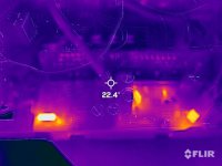
So given that the PSU behaves with just the power amp board disconnected and there was only a problem on the B- side is the best course of action to de-solder the transistors that might have failed and test them?
According to the magic camera, both Q313 and Q363 are conducting hard when the 100v line is attached (the blue line) If the purple resistor track was the route cause I'd expect both +ve and -ve rails to be wonky That said if I've done something on the PSU side it would affect both channels - stereo trouble
I don't really want to de-solder old transistors just to check them, is there anything else that could be making the negative side go bananas?
Andy
Attachments
Hi Andy,
Have you checked all caps are correct polarity vs schematic ( theme building here).. I think it may need to be a process of elimination with the transistors to see if one is shonky.
I am starting to feel very lucky with both my amps in that they seem to have avoided the problems you are facing.
jon
Have you checked all caps are correct polarity vs schematic ( theme building here).. I think it may need to be a process of elimination with the transistors to see if one is shonky.
I am starting to feel very lucky with both my amps in that they seem to have avoided the problems you are facing.
jon
I have and since I'm in the very fortunate position of being able to compare TA-5650 amps too, everything checks out visually as far as I can tellHave you checked all caps are correct polarity vs schematic ( theme building here).. I think it may need to be a process of elimination with the transistors to see if one is shonky.
Incidentally I replaced the signal path electrolytic's with films in the "first refurb" today - the woodsided one. (https://www.diyaudio.com/community/threads/another-sony-ta-4650-v-fet-thread.376634/post-6839093) Just to get that over with and do said comparison all switches cleaned, Volume pot replaced with a deep cleaned version
I would say there is more low end. At least, I no longer feel compelled to have the loudness filter switched in! However, the TA-5650 still needs about a 12th more volume than the TA-4650 to do similar listening levels. @jonboylaw do have the same observation?
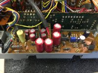
Pics of the innards attached 🤓 Signal caps on the Power amp board installed to avoid chimney supports (thanks again Jon.) I fitted plastic insulator on the leg over the resistors to prevent any opportunity for shorts.
Andy
Attachments

I am starting to feel very lucky with both my amps in that they seem to have avoided the problems you are facing.
It's more me being 'unlucky' 🤣
First one was a doddle. The 4650 would have been simple too except for my busting stuff on the way - it was bought as a deaddie though
This
 one is fighting...
And fighting...
Removed all transistors on the B- side supply to the class B amp so
Q363, Q313 (2SC1663)
Q361,Q311 (2SA639S)
All are fine 😵 which was NOT supposed to happen...
So things I know / can assume
Am I missing a trick with the PSU board / voltage doubler?
Next steps:
Waiting for the decent screw terminals to arrive, so bear with me.
Andy
Removed all transistors on the B- side supply to the class B amp so
Q363, Q313 (2SC1663)
Q361,Q311 (2SA639S)
All are fine 😵 which was NOT supposed to happen...
So things I know / can assume
- I know I had the +97 and 0v rails swapped PSU board to EQ board connector - see earlier in this thread.
- Replaced PSU board for a spare with replaced caps and pass transistors seems to be ok. Or at least voltages good with everything connected Except the main amp board
- The problem is only with the -97v rail. It's dropping (climbing) to -65v. The +97v rail is as should be
- The problem occurs only when the AMP board is attached. Figures, since the B-line only goes there from the PSU board
Am I missing a trick with the PSU board / voltage doubler?
Next steps:
- Replace wire wrap connector on the PSU board(s) with screw terminals - at least in the short term
- re-connect and re-check just in case I've re-soldered a bad joint
- Try both PSU boards
- Disconnect the B-link wire on the Amp board to see if that narrows it down to at least one channel
- If not, one option is to bin the whole amp board and use a spare. but that feels a bit square one
Waiting for the decent screw terminals to arrive, so bear with me.
Andy
Andy,
Swap the main filter caps (10000uF), B+ for B- side and see if the +ve rail drops when the power amp board is attached. Could be a duff main filter cap causing a droop. Then look at the rectifier diodes to see if they are all in good order. Finally, is the transformer ok???
Jon
Swap the main filter caps (10000uF), B+ for B- side and see if the +ve rail drops when the power amp board is attached. Could be a duff main filter cap causing a droop. Then look at the rectifier diodes to see if they are all in good order. Finally, is the transformer ok???
Jon
- Home
- Amplifiers
- Solid State
- Complimentary ramblings AKA another Sony TA-5650 V-Fet thread