Please, give me some remarqs off this circuit.
I've always used BJT's but many off you made me curious about using JFET's.
Jfet's should be cascoded to minimize the voltage differences between drain and source to keep the input capacitance relative low.
But I've seen many circuit's where the Jfet is cascoded with another Jfet. This way you'll have about 0.7V as VDS for the Jfet. When I see in the datasheets, I will have then pretty hich input capacitance. So I wanted to cascode the Jfet with a BJT, this way I could have a VDS for the Jfet off about 3.5 to 4 volts when using 2 LED's.
What do you guys think off this differential input circuit? Or should I just use two Jfet's instead of Jfet + BJT.
Greetz
Ben
Attachments
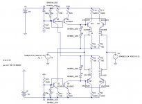
I've got the idea off the SERVO 50 amplifier off Borbely.
And Mr. Curl has me convinced to use complemantary diff input instead of single diff, while he is using this in his Halo JC1 amp.
http://www.borbelyaudio.com/special_articles.asp
And Mr. Curl has me convinced to use complemantary diff input instead of single diff, while he is using this in his Halo JC1 amp.
http://www.borbelyaudio.com/special_articles.asp
Hi Benson,
There are several good threads on cascodes and folded cascodes. The thread below cites several good papers and provides some data comparing FET-FET, FET-Bipolar, and Bipolar-Bipolar cascodes. There are also threads on "modulated cascodes" using FET-FET topologies that you might find interesting. I've been using a JFET-Bipolar folded cascode topology with good results in my power amps.
http://www.diyaudio.com/forums/showthread.php?s=&threadid=63187&perpage=10&pagenumber=2
LineSource,
Yes, I had read that thread already, but for a non EE is it pretty hard to understand sometimes. But in post#18, Forr is explaining a circuit that for me looks like the one I've drawn.
Is in my circuit the CCS for the diff pair exually needed, I use a regulated power supply for the diff pair. And can I than connect the four resistors with each other? ...Oh wait, than I have the Borbely amp 😀
This should make things a bit more easier.
I used two LED's in series for biasing the cascode BJT, is a simple resistor or zener maybe better? Noise? Osscilation?
Thanks
Ben
Hi Benson,
One of the good things about the FET/BJT cascode as in your pic is that it doesn't need the CCs's for biassing and a simple R tail between the two halves can set the bias.
The best CCS is no CCS. You still need to bias the cascode though.
Cheers,
Greg
One of the good things about the FET/BJT cascode as in your pic is that it doesn't need the CCs's for biassing and a simple R tail between the two halves can set the bias.
The best CCS is no CCS. You still need to bias the cascode though.
Cheers,
Greg
Hi Bensen,
I too have read Borbely and agree that the logic for connecting the cascode to the LTP tail is well founded.
I think you have made the correct decision to cascode this way rather than using ground for the cascode reference.
The two current sources (& two sinks) do seem a little complicated and maybe Guru is right to remove the tail sink/source and just keep the cascode source. But with a regulated PSU even a resistor here should be adequate to feed the two LED string.
However, keep the PCB as you have drawn and compare the four versions;- all ccs, all resistor, ccs to cascode and resistor to LTP, ccs to LTP and resistor to cascode. Then you can publish the sound quality effect of your experiments. I will be waiting.
ps I will send back the latest version of SOAR.
Hi Benson,
There could be an opportunity to bias the cascode from a modulated driver as in my latest design which not only eliminates the need for the CCs but benefits from a 3 times reduction in THD - why wouldn't you?
Cheers,
Greg
There could be an opportunity to bias the cascode from a modulated driver as in my latest design which not only eliminates the need for the CCs but benefits from a 3 times reduction in THD - why wouldn't you?
Cheers,
Greg
Hi amplifierguru ,
I've did yesterday a search for "modulated cascode" but found nothing interesting. Have you maybe a link to some sort of circuit where did is used.
I remerber that you' ve writin some where that you used the current throught the VAS also for biasing the diff pair.
Thanks for the reply.
Ben
I've did yesterday a search for "modulated cascode" but found nothing interesting. Have you maybe a link to some sort of circuit where did is used.
I remerber that you' ve writin some where that you used the current throught the VAS also for biasing the diff pair.
Thanks for the reply.
Ben
Hi AndrewT,
You mean by referencing to ground, something like in the attached pic I presume.
But, this gives me one very big advantage. Namely, this way I can supply the diff input pair with a regulated PS +-75V , without destroying the JFET's due to overvoltage, and have a large enouph output swing for the second stage. Otherwise I have to use some kind of circuit posted in the next post.
But this cascode give me more voltage variations over the Jfet --> input capacitance raises.
Attachments

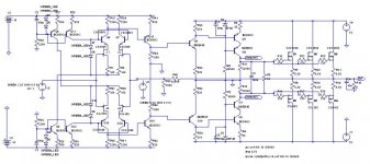
Bensen said:This is the topology I should use when I would supply the diff pair with only 15volts. Don't mind the resistor values....
I think always that: the less stages there are in an amp the better.
Hi Bensen,
why so many VAS's?
Cheers Michael
Well,
When I would connect the outputs off the diff pair directly to the Cascoded VAS (BC... +MJE...), there would be to much current taken away out off one leg off the diff pair.
I want to bias the cascoded VAS to about 30mA, and when I fet the diff pair with only 15volts, and the VAS with 75V, I would need many volts over the collector resistors from the diff pair to bias the VAS that way.
I can live with a current of max 50µA leaving out of one leg.
The first stage after the diff pair services as some kind of buffer to not source to many µA out off the diff pair AND also gives me a phaseshift of 180° degrees which I need. The following stage makes it possible to give a decent output voltage for the cascoded VAS. This one needs a signal with a DC offset off about 70 to 75V.
Well, I've said I'm not an electronic engineer. So this could be made probably much better and easier. But I'm still learning the art of amp designing.
This circuit is just a try to have an idea how an amp works, and what to do to get a "nice" output signal.
First a want to focus on the diff pair. For the VAS I will surely use a Casoded one and than lateral mosfet's.
Greetz
Ben
hey greg:
say a little more about this approach, if you don't mind.
i saw jcarr mentioned in another thread some very interesting (as in good) THD results doing something like this also.
mlloyd1
(who, by the way, really likes his Servo 50 😉 )
say a little more about this approach, if you don't mind.
i saw jcarr mentioned in another thread some very interesting (as in good) THD results doing something like this also.
mlloyd1
(who, by the way, really likes his Servo 50 😉 )
amplifierguru said:Hi Benson,
There could be an opportunity to bias the cascode from a modulated driver as in my latest design which not only eliminates the need for the CCs but benefits from a 3 times reduction in THD - why wouldn't you?
Cheers,
Greg
Bensen,
ok I see, you have a "level shifting" issue here! 😀
I don't think there's any problem connect the diffpair collector resistors directly to the outputstages rail voltage as such.
It would be more important to have a "buffer" after VAS than before me thinks.
Mlloyd1,
perhaps this is what we are looking for, Greg's Luscious New Design? 🙂
Cheers Michael
Ultima Thule said:
I don't think there's any problem connect the diffpair collector resistors directly to the outputstages rail voltage as such.
Oh, I think this should be risky, the max VCE is 80V for these devices. And with this circuit they would have about 70V.
"mlloyd1
(who, by the way, really likes his Servo 50 )"
Do you mean that this kind of diff stage doesn't sound that good?
quite the opposite,
i think mr. borbely did a fabulous job with his designs.
"i built the servo 50 some years ago and i still like it" is really the message i wanted to convey.
mlloyd1
i think mr. borbely did a fabulous job with his designs.
"i built the servo 50 some years ago and i still like it" is really the message i wanted to convey.
mlloyd1
Bensen said:
...
"mlloyd1
(who, by the way, really likes his Servo 50 )"
Do you mean that this kind of diff stage doesn't sound that good?
Hi again,
Am I correct when I say that an amplifier with Jfet input doens't need such a big voltage gain than one with BJT's as dif input? Because a Jfet is much more lineair than a BJT.
I ask this question because it is not that easy to design an amp with high voltage gain with Jfet input. I just ordered 6 X2SK389BL and 6 x 2SJ109BL, and I would really like to use these.
With a diff input like the one used in the dc-102 design from Borbely, connected with a second diff pair it is pretty easy to have relative high voltage gain (X40).
When one would use a differentiall VAS (like the AEM6000), there is no problem. In the thread "simple killer amp", amplifierguru says, that it's best to have the highest gain in the stage with the error correction. Which seems logical to me.
Greetz
Ben
Bensen said:Hi again,
Am I correct when I say that an amplifier with Jfet input doens't need such a big voltage gain than one with BJT's as dif input? Because a Jfet is much more lineair than a BJT.
Ben
No, less gain from a fet diff pair will result in less loop gain = less feedback around all of the other stages, (esp the output) and more distortion
http://www.diyaudio.com/forums/showthread.php?s=&postid=501789&highlight=#post501789
shows how the usual fet/bjt "comparison" is skewed (or corrected) by playing with extra gain from later stages
input stage distortion is rarely a problem if slew limiting is avoided so "linearizing" the diff pair and using the lower loop gain will be a net loss
high global loop gain gives the greatest distortion reduction compared to "wrapping up" the same total gain in local loops with reduced global feedback
Thanks JCX,
I've redesigned the amp. And I've come to the following topology (see pic). But many off you guys are saying that a buffer after the VAS is an advantage, as the output devices seeing a much lower impedance.
What are you guys thinking of mine amp, does I really need that buffer, because it's giving oscilations. Don't look at the values of the resistors from this buffer, this pic is taking during simulations.
Or, do you think it would be better to definitely use this buffer. Or maybe I should design it different.
BTW: the gain is +-20000 X
Greetz
Ben
Attachments
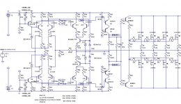
I see that when I use a MJE150XX or the BD139/140 combination instead of the MJE340/350, I got ridd of the oscillations. But when I checked the datasheet of the MJE150xx serie, I see that these like to work on higher bias, but throught the buffer is running about 30mA.
1) Is 30mA enouph?
2) Which transistor combination looks the best fit to you?
3) Why is this (oscillaton dissappears)?
Thanks
Ben
1) Is 30mA enouph?
2) Which transistor combination looks the best fit to you?
3) Why is this (oscillaton dissappears)?
Thanks
Ben
- Status
- Not open for further replies.
- Home
- Amplifiers
- Solid State
- Complementary diff input with JFET and BJT cascode