Hi all.
Problem:
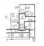
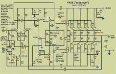
In this circuit, C8 gets the benefit of the Miller Effect because there's voltage swing at the collector of Q5, while C7 does not show the same effect because there was very little voltage swing at the collector of Q4.
Which is the best solution? I have seen different solutions. What is the most effective compensation and best sound?
Problem:
In this circuit, C8 gets the benefit of the Miller Effect because there's voltage swing at the collector of Q5, while C7 does not show the same effect because there was very little voltage swing at the collector of Q4.
Which is the best solution? I have seen different solutions. What is the most effective compensation and best sound?
Attachments


Well, if the voltage swing between two nodes is limited, as is the case in a number of the circuits above, there is no point in trying to use a miller cap across those two nodes - you acheive nothing.
For the balanced VAS, I've seen a few examples where only one cap is use from the actual VAS output, back to the associated LTP collector.
Another option here is to forget about miller comp and try some other approaches:-
Cordell Audio: Papers: A MOSFET Power Amplifier with Error Correction
For the balanced VAS, I've seen a few examples where only one cap is use from the actual VAS output, back to the associated LTP collector.
Another option here is to forget about miller comp and try some other approaches:-
Cordell Audio: Papers: A MOSFET Power Amplifier with Error Correction
Any comments are welcome.
Thanks
Guillermo
Here is the new one. This works the best for the mongrel. The Kenwood / denons are built around older devices. What compensations are used depends on what is driving it (the VAS) and what it is driving (MOSFETs ,EF2 or TRIPLE OPS).
I have seen 20 other techniques (including Cordells).
All of them work , BUT some sound different , are more stable (VERY device dependant) , and some are just CRAZY , like the shunt comp. on the symasym or the Denon 2000 (they sound the best .. ironically).
OS
Attachments

IMO the only reasonable connection of this capacitor is from base to ground. Check the PSRR improvement you get.
Samuel
Samuel
IMO the only reasonable connection of this capacitor is from base to ground. Check the PSRR improvement you get.
Samuel
Right! The only other option is, as Bonsai said already, a small cap from the VAS output to inverting input of the IPS.
Making a really balanced Miller compensation (that is, two equal caps and the same voltage but in anti phase across them) is hard to realize, for the simple reason that you don't have an inverted copy of the VAS output voltage at hand.
Cheers,
E.
Hi Geirin
Sorry, I can't read the latest schematic, but can comment on some earlier ones.
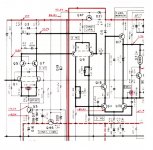
In the schematic from post 1 (first pic below), C8 is the compensation capacitor, and C7 is to improve PSRR of the positive rail. I explained how that works here: http://www.diyaudio.com/forums/solid-state/169590-mongrel-supersym-ii-19.html#post2254135
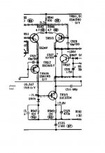
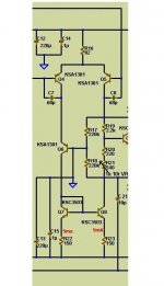
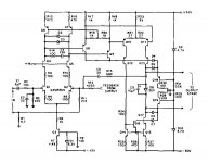
The circuit from post 5 (2'nd pic below) is similar but without the cascode C7 is connected directly to the mirror on the negative rail. In this case, C7 still improves PSRR of the positive rail, but makes PSRR of the negative rail worse.
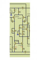
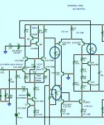
In the circuit from post 4 (3'rd pic below), the 220pF cap (C3) is the wrong value and it's connected to the wrong side of the cascode. It makes PSRR very much worse for both positive and negative rails.
To understand PSRR, it helps to forget about the wanted signal for a moment and just concentrate on the unwanted ripple.
For example, in the first pic below, the bases of Q4 and Q5 are held at a constant voltage below the positive supply rail, so when there is ripple on the positive rail, it will also be on those bases. Because there is ripple voltage across C7 and C8, ripple current flows through them.
In the 3'rd pic below, if there is ripple voltage on either the positive or negative rails, a relatively large amount of ripple current will flow through the 220pF cap.
Apologies for all the OT. I know you were asking about compensation not PSRR, but it doesn't hurt to think about what those other caps are doing too.
Cheers - Godfrey
Sorry, I can't read the latest schematic, but can comment on some earlier ones.
In the schematic from post 1 (first pic below), C8 is the compensation capacitor, and C7 is to improve PSRR of the positive rail. I explained how that works here: http://www.diyaudio.com/forums/solid-state/169590-mongrel-supersym-ii-19.html#post2254135
The circuit from post 5 (2'nd pic below) is similar but without the cascode C7 is connected directly to the mirror on the negative rail. In this case, C7 still improves PSRR of the positive rail, but makes PSRR of the negative rail worse.
In the circuit from post 4 (3'rd pic below), the 220pF cap (C3) is the wrong value and it's connected to the wrong side of the cascode. It makes PSRR very much worse for both positive and negative rails.
To understand PSRR, it helps to forget about the wanted signal for a moment and just concentrate on the unwanted ripple.
For example, in the first pic below, the bases of Q4 and Q5 are held at a constant voltage below the positive supply rail, so when there is ripple on the positive rail, it will also be on those bases. Because there is ripple voltage across C7 and C8, ripple current flows through them.
In the 3'rd pic below, if there is ripple voltage on either the positive or negative rails, a relatively large amount of ripple current will flow through the 220pF cap.
Apologies for all the OT. I know you were asking about compensation not PSRR, but it doesn't hurt to think about what those other caps are doing too.
Cheers - Godfrey
Attachments

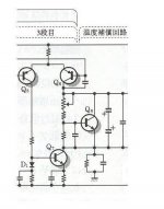
btw, similar tricks can be used to improve PSRR with other topologies.
Shown below is part of a typical "Blameless" style amp. Cdom is the compensation cap and Cpsrr has been added to improve PSRR.
(Hope Carlos doesn't mind me butchering one of his schematics)😱
Shown below is part of a typical "Blameless" style amp. Cdom is the compensation cap and Cpsrr has been added to improve PSRR.
(Hope Carlos doesn't mind me butchering one of his schematics)😱
Attachments
C6 + R13 is not a filter as such.
It is a gain limiter.
It is NFB inside the LTP loop.
R13//680r sets the LTP gain when C6 has low impedance, i.e. at very high frequencies.
680r alone sets the LTP gain when C6 has a high impedance, i.e. at very low frequencies. It is a sort of step in the frequency response (or should that be gain response?).
It has the same effect as reducing the OLG @ HF to allow the overall feedback to remain stable.
AndrewT
Your explanation is very very clear. Thanks.
So, capacitors C7 and C8 are unnecessary for compensation?
And is necessary phase lead?
This is the configuration that uses Bob Cordell, R + C in LTP and R+C as a phase lead. This RC phase lead has the same function as the RC in LTP?
Your explanation is very very clear. Thanks.
So, capacitors C7 and C8 are unnecessary for compensation?
And is necessary phase lead?
This is the configuration that uses Bob Cordell, R + C in LTP and R+C as a phase lead. This RC phase lead has the same function as the RC in LTP?
Attachments
- Status
- Not open for further replies.
- Home
- Amplifiers
- Solid State
- Compensation in balanced VAS