Hi,
I'm trying to subtract the volume within the cone and baffle cut-out from the throat section of my TH (still in the design stages). I would like the volume within the enclosure to match what was simulated in Hornresp.
I read in the THAM 15 tread that this is called 'cone correction' and saw that pieces of wood was used in the throat section to displace the volume taken up within the cone.
However I was thinking of reducing S1 thru S2 to compensate for the additional volume within the cone and baffle cut-out, by doing this I could simultaneously increase the mouth size to compensate for the displacement of the rear of the driver also (my folding scheme is same as the THAM 15).
Would this work or would this just increase the compression ratio? I really don't want to risk damaging the driver.
Thanks.
Last edited:
Whether you call it "cone correction" or simply "doing an accurate simulation" the volume of air in the cone must be accounted for or the sim won't be accurate.
Most people just add a throat chamber in Hornresp (Vtc and Atc) to account for this volume of air. Or you can add in little blocks of wood to displace this volume although I've seen no proof that it does anything beneficial at all except make the sim more accurate for those that don't want to use a throat chamber.
Danley's TH118 uses the cone volume as part of the horn flare path like so:

The second pic isn't the Danley design (not sure what it is) but it's easy to see the restriction at S2 as the path flows through the cone.
Last edited:
Danley's TH118 uses the cone volume as part of the horn flare path
That's clever!
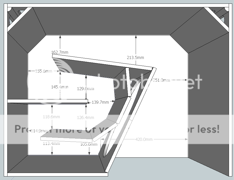
So would reducing the volume in the throat section (shaded in red as shown in my sketch) be just as a good as adding pieces of wood to compensate for the added volume, in this way I'd kill two birds with one stone as I'd open up the volume in the mouth section at the same time to accommodate the volume of the magnet at the back of the driver (i'm talking about modifying the drawing here not the sim)
thanks


Last edited:
Well... the cone is V shaped so there's no real way to make you (white background) drawing have a "cone correction" without using blocks of wood. In your second drawing you could reduce the path length cross sectional area a bit but it still wouldn't be V shaped, not the same shape as the cone. You would have to lay it out like the TH118 or something very similar to that to get the V shape.
Anyways, the volume of air in the cone is something like maybe 5 liters and the cross sectional area is maybe 1/2 Sd or less. Is that going to make any significant difference if you add that to the mouth?
Anyways, the volume of air in the cone is something like maybe 5 liters and the cross sectional area is maybe 1/2 Sd or less. Is that going to make any significant difference if you add that to the mouth?
I've seen no proof that it does anything beneficial at all except make the sim more accurate for those that don't want to use a throat chamber.
It did flatten out a dip in the response at the upper end of the passband for my POC3 TH. I think I published the results here in another thread.
Too much "cone correction" however will reduce efficiency among other things. I showed that in another thread 🙂.
If starting a design, it might be easiest to just account for it using Vtc and Atc as you suggested, unless your sim shows better results if it does not have a throat chamber.
Thanks just a guy, I'll revisit my CAD drawings and see what I can come up with that's more V shaped, if not I'll just use the blocks of wood, that way I could do some measurements before & after I add the blocks and see what difference it makes.
Probably not much difference, but I was thinking it's better than none! BTW you are right the volume to be compensated for is 4.96 litres!
Anyways, the volume of air in the cone is something like maybe 5 liters and the cross sectional area is maybe 1/2 Sd or less. Is that going to make any significant difference if you add that to the mouth?
Probably not much difference, but I was thinking it's better than none! BTW you are right the volume to be compensated for is 4.96 litres!
It did flatten out a dip in the response at the upper end of the passband for my POC3 TH. I think I published the results here in another thread.
Too much "cone correction" however will reduce efficiency among other things. I showed that in another thread 🙂.
If starting a design, it might be easiest to just account for it using Vtc and Atc as you suggested, unless your sim shows better results if it does not have a throat chamber.
Hi Brian,
I simmed a TH using your SFTH3 sheet and hornresp. From all I've read in the threads and what you say here, I understand that "cone correction" is done by entering the driver diaphragm volume into the Vtc field (which your sheet calculated) and Atc, which would normally be "0" for a tapped horn? Did I understand this correctly? If that is correct, then if we enter the cone volume for Vtc, we don't have to "pinch" S2 I gather?
And how can we compensate for the cone volume when calculating the compression ratio?
Best,
Selim
Last edited:
Hmm, 'pinching' S2 to whatever gives the desired compression ratio works with S2, S3 set to manual after initial sim, but no combination of Atc/Vtc works.
GM
GM
Thank you GM. I calculate the compression ratio by dividing the cone area to the S2. Does the baffle cutout and the cone volume have any effect on this?
You're welcome!
Correct and shown down in the Notes bar at the bottom when S2 is highlighted, so no need to 'do the math' 😉.
No, just adds a low pass filter.
GM
Correct and shown down in the Notes bar at the bottom when S2 is highlighted, so no need to 'do the math' 😉.
No, just adds a low pass filter.
GM
Great, thanks again GM. I'm making a single driver 8" MCM 55-2421 single fold TH. Once built and tested I'll share the design and results. Any thoughts on which thread to post it on or, shoud I start new thread?
Best,
Selim
Best,
Selim
You're welcome!
Assuming no big thread devoted to it, personally prefer a new thread which allows searches for threads instead of having potentially mass quantities to comb through if having to search posts, so please put the driver/alignment info in the title.
GM
Assuming no big thread devoted to it, personally prefer a new thread which allows searches for threads instead of having potentially mass quantities to comb through if having to search posts, so please put the driver/alignment info in the title.
GM
- Home
- Loudspeakers
- Subwoofers
- Compensating for cone volume in TH