That model is interesting. I guess multiple poles of eddy loss? And then the capacitor makes sense; I wondered about that in the standard LR model.
I guess my attitude is that any amount of capacitors resistors and inductors form an LTI system, which can be modeled with a series of poles and zeros, some of them second order. Therefore this can be perfectly undone with the reciprocal input filter. We can tackle these one at a time, moving from low to high frequency, and we should get incremental improvement at each point, as long as we are careful not to undo a pole that was hiding a nasty peak without also undoing that peak, and not to undo a pole in such a way that we create infinite gain at high frequencies.
Of course if you're altering the loading in order to try and intentionally produce something that's more easily compensated for, this model becomes much more important.
Why we haven't considered. A lot of work to do but it's interesting how different approaches to the generator design change the electrical model and HF performance. What has been most interesting for me is to discover that a lot of the alternative loading schemes that have been discussed over the years don't work well with an accurate cartridge model. Annoying for me as I would love to run my MM with a current mode phono state (and probably still will my AT just to be difficult). But the discovery is fun even if it's flogging a dead horse 🙂That model is interesting. I guess multiple poles of eddy loss? And then the capacitor makes sense; I wondered about that in the standard LR model.

Hmmm ok so sounds like the compensation might work, but if so the calculated values will likely be off.
Since you're amenable to dsping your way out, seems like you could just lift the ground and inject a signal there instead, look at the resulting frequency/phase response, and make a big FIR filter to compensate. Not exactly an elegant solution, but that should deal with the electrical bits anyway. Or are you saying that the electrical bits are going to behave differently in their response to a changing magnetic flux than to a changing input voltage? That would make some sense. LT spice allows you to inject flux into one inductor by coupling it with another. I've been wondering whether something there might give a better model of the response, somehow. Throwing the input voltage into an integrator then convert it to current through an inductor in an opamp loop simulates an ideal injection of flux. So far it does look like there's subtle differences in LTSpice doing this with an inductor w esr vs a voltage source followed by an inductor and resistor, but they look small enough that I'm not sure this is a difference in model predictions rather than just some differing sources of error in ltspice. And anyway not significant enough to worry about. But there might be some way to get this closer to reality by coupling several inductors to the same flux source.
Just thinking about it, it seems as though the magnet will be closer to one part of the coil than another, so what you'll get is not actually a uniform distribution of flux throughout the inductor but a hot spot which is acting as a generator and cool spots without flux acting as pure inductances. That could end up behaving very differently than a simple inductor. Plus also the dflux might have more or less losses when the magnet is closer or further from the coil--but seems like this would show up as THD.
Anyway, seems like what I actually would want to do is forget about all this complexity, instead decide how complex I want the compensation to be, measure the frequency output, and then do a best fit to whatever that level of complexity is. A second order seems like it's probably still a pretty good approximation, so long as we just want to flatten out like 17k to 27k or so.
I know that this may amount to an apples to oranges comparison but I was very surprised to see the cartridge used here being an AT95. I own an AT 95SA remake from LP gear and while I get very good results with one phono pre that I built (Pete Millett design), I am having trouble with a different phono pre that I have built, namely the Aikido PH2 Phono pre, designed by John Broskie. In short, I suspect that at least some of the trouble may due to the loading of the cart, but likely there is something else amiss. It sounds hollow, with a big drop in bass. The mids are very forward as well as the treble. Any thoughts about this problem? Most of what has been posted is pretty much above my level and like I said, this may not be a good example to question in this thread, but I am in deep with both money and time, so I am asking for help. Thanks in advance for your responses.
Hey, thanks guys for thew quick responses!
billshurv, I will find out what options there might be for the phono. I seem to remember that 100 pf being a general target but it was also assumed that the phono cable would be accounting for most of that. This seems to me to be the first thing to check in this case.
rayma,
When building this unit, I went with the best that I could find, i.e. mostly Vishay and then of course the resistors that JB supplies with the kit. Metal film, all 1% even where it is not a big deal. It is a good point though.
I dedicated this build to my father, and so didn't want to spare expenses just for that reason alone.

Very nice.
Did you use the proper tubes, and the proper value of R12 for them?
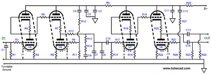
What about the RIAA capacitors C7, C8, and C9, which as just as important as the resistors?
They should all be 1% tolerance as well.
Also duplicate the loading from the Millett preamp before comparing.
Did you use the proper tubes, and the proper value of R12 for them?
What about the RIAA capacitors C7, C8, and C9, which as just as important as the resistors?
They should all be 1% tolerance as well.
Also duplicate the loading from the Millett preamp before comparing.
Last edited:
rayma,
Again, thank you so much for your response. There are times that if a question is asked, you can just about forget it as far as responses go. Your insight tells me that you have good experience here. I can only answer this way. I used the components that were sent to me from Mr. Broskie. All were quality parts and that is always appreciated. Since I measured 6.9 volts for the heaters I can then confirm that all of the tubes were JJ 6GM8, as sent from Broskie/Glassware. It has been long enough that I have to take a second glance here. R12 was chosen for the proper value to the tubes. It is of course important that I got that part correct.
You gave me a good idea in taking a closer look at the P. Millett pre. The cartridge sounded very good with that phono pre.
Interestingly to me, there has been an update about the performance/sound of this pre. I have never had it on for a very long time since it sounded awful. Today however, I let it warm up for 20 minutes before playing. Yup, it sounded awful. I left it on still another hour and am embarrassed to admit that the sound greatly improved. Bass is almost all the way there (I am used to my system being bass heavy so this may be a good thing). Treble is still bright, but well within adjustment. And the midrange is that which I have never heard before on vinyl.
Having said this and have owned a number tube equipment, I couldn't be more surprised at the time it took for the unit to 'warm up'. Really? 1 1/2 hours? My Glassware Aikido line stage (12AX7 tubes if that matters) doesn't need more than maybe 5 minutes. It sounds better than I can explain here, but yes, all is well with it in 5 minutes. Not a rant but much of a surprise to me. Of course, I will try some 100 pf caps and see what it gets me, but at this point, I don't have that far to go. I will post my progress.
try taking the input loading caps out all together. Your cabling has more than enough capacitance.
Some don't think a warm-up is necessary, but experience shows otherwise.
If you do not use the preamps regularly, leave them on for at least several hours before proceeding.
Then a reasonable warm-up before each use should be ok, 30 minutes or so.
You have a nicely scientific attitude, it will take you far.
If you do not use the preamps regularly, leave them on for at least several hours before proceeding.
Then a reasonable warm-up before each use should be ok, 30 minutes or so.
You have a nicely scientific attitude, it will take you far.
Last edited:
@Ixnay Your question is exposing me for fixing things which aren't problems... (maybe that's how progress is made? maybe I just have ocd? maybe ocd is how progress is made?) It's actually the reported and experienced good behavior of this cart wrt loading that makes me think it might be well behaved enough to gain something from compensation, rather than being some bad behavior that I'm trying to fix.
On my table, the AT sounds great, even though my current preamp is kind of shitty (hence wandering into this hole while designing a mark 2). I started out with way too much cable capacitance (long story), like 200p, plus like 220p in the amp; I've since clipped off the capacitors in the amp and got the cable capacitance down to 150p. As expected, it sounds more extended, and subjectively a touch brighter, but overall even such a radical difference of 420p to 150p is pretty subtle. You've double-checked all your table parameters, like VTA, weight, etc, correct? Others seem to know the amp better than I do, but I'd just add, you might try and eyeball the traces and the solder joints, and jiggle the wires to make sure that's not a problem. It's possible you got an iffy connection that manifests as series capacitance.
On my table, the AT sounds great, even though my current preamp is kind of shitty (hence wandering into this hole while designing a mark 2). I started out with way too much cable capacitance (long story), like 200p, plus like 220p in the amp; I've since clipped off the capacitors in the amp and got the cable capacitance down to 150p. As expected, it sounds more extended, and subjectively a touch brighter, but overall even such a radical difference of 420p to 150p is pretty subtle. You've double-checked all your table parameters, like VTA, weight, etc, correct? Others seem to know the amp better than I do, but I'd just add, you might try and eyeball the traces and the solder joints, and jiggle the wires to make sure that's not a problem. It's possible you got an iffy connection that manifests as series capacitance.
Again, all advice has been greatly appreciated. And yes, true to form, after I had turned off the phono pre for several hours and then turned it back on, the same results occurred. This time I wasn't surprised or panicked and know the procedure from here on out.
As it turns out, there is not an internal capacitor for cart loading inside the amp and that is fine. I still do not know for sure the pre input impedance, but it seems that one time when I measured it 47k came out to be the result.
Anyway, I consider this to be the end of my confusion for the subject and am very happy that things turned out as they did. FWIW, I am doing a little work on the line level preamp to add an output for the sub, and to adjust the input for the phono pre, as it is padded down quite a bit. The line level pre has a lot of gain, and that is why the inputs are padded.
- Home
- Source & Line
- Analogue Source
- Compensating for cartridge response in the phono stage