As we know, the inductance of the cartridge couples with the parallel total input capacitance and input resistance to form an RLC lowpass filter. But seeing as we're already doing all kinds of eq in the preamp, why not add a couple extra time constants to compensate for that filtering? I'm exploring a preamp design that does just that. Bad idea? Good idea? Weird idea? Curious what people's take is. I haven't built this yet, but unless you all dissuade me I will soon.
Obvious problems: (1) The cartridge might be using these poles to compensate for the mechanical response. Maybe. However then again it might not. (2) Variation from the published specs makes this an imprecise target. In simulation, this actually seems not to be a problem, and anyway variation will affect the sound without compensation as well. (3) It's not universal. Yep. However, see previous: variation within a range may still be useful. (4) You're amplifying high frequency noise. I'm not sure how much of an issue this is, but we will want to limit how far up those extra time constants reach anyway for stability reasons
Anyway, here's the design thinking:
I. Cartridge specs and input
I'm designing this for an AT VM95 cartridge. Inductance is 550mH, resistance is 485 ohms. The first step is to determine what's going on with the loading recommendations and how we want to load it. Frequency response measurements of this cart seem to pretty closely match what you would expect from the RLC filter alone. The filter achieves a Butterworth condition at around 125pF/47k input impedance, so capacitance above that will be a little peaky, and below that a little more rolled off. That seems to match what I've seen in measurements on the web. All of this indicates that it is unlikely that this particular cartridge is using the impedance to compensate for its response curve.
Since I've already thrown compatibility out the window, we may as well set capacitance and resistance to whatever we want. Since we're going to compensate the roll off, smoother curves will respond better to component differences. And anyway the circuit I'm using won't compensate anything above a Q of 0.5. There's no reason to intentionally load with capacitance at all, since we can adjust the resistor to get the desired Q. Currently my setup is a bit above this, but I'm going to guess that with a good cable I can get total input capacitance down to 100p. We're going to shoot for a Q of 0.47. The nearest resistance is 34.8k, giving a Q of 0.47 and a frequency of 21.6kHz.
II. The circuit

Just the bog standard single opamp stage, with an extra resistor and capacitor. Note that in practice you will need to modify this to control DC offset, but this gets the point across. The differences from the standard circuit are (1) we are not following this with a resistor/capacitor; that time constant is being used for compensation. (2) We're adding extra high frequency boost with Cb, limited by Rb. To get these values, I wrote out the Laplace equations for current along the feedback path, then used an algebraic solver to cut through the mess, and finally hand-tweaked to get the errors where I want them. But basically (almost), Cb//R1 sets the compensation frequency, R2 sets the Q, Cb Rb should be set where you want high frequency roll off to begin, and the rest is as you would normally design it. Cb Rb has to be reasonable if you want your amplifier to be stable.
III. Results
Until I build and test it, there's no way of knowing how this will stack up in practice. But I've attached some graphs showing the electrical response, anyway. The first two show two different views of the RIAA curve including the cartridge response. The last shows the compensation curve without the cartridge, with a larger frequency range. (The roll off is way further than you'd need, but it does affect the accuracy of the frequency response much lower down.) Electrically, this stage, including the cartridge response, will be flat +- 1dB to 96kHz!!!


Obvious problems: (1) The cartridge might be using these poles to compensate for the mechanical response. Maybe. However then again it might not. (2) Variation from the published specs makes this an imprecise target. In simulation, this actually seems not to be a problem, and anyway variation will affect the sound without compensation as well. (3) It's not universal. Yep. However, see previous: variation within a range may still be useful. (4) You're amplifying high frequency noise. I'm not sure how much of an issue this is, but we will want to limit how far up those extra time constants reach anyway for stability reasons
Anyway, here's the design thinking:
I. Cartridge specs and input
I'm designing this for an AT VM95 cartridge. Inductance is 550mH, resistance is 485 ohms. The first step is to determine what's going on with the loading recommendations and how we want to load it. Frequency response measurements of this cart seem to pretty closely match what you would expect from the RLC filter alone. The filter achieves a Butterworth condition at around 125pF/47k input impedance, so capacitance above that will be a little peaky, and below that a little more rolled off. That seems to match what I've seen in measurements on the web. All of this indicates that it is unlikely that this particular cartridge is using the impedance to compensate for its response curve.
Since I've already thrown compatibility out the window, we may as well set capacitance and resistance to whatever we want. Since we're going to compensate the roll off, smoother curves will respond better to component differences. And anyway the circuit I'm using won't compensate anything above a Q of 0.5. There's no reason to intentionally load with capacitance at all, since we can adjust the resistor to get the desired Q. Currently my setup is a bit above this, but I'm going to guess that with a good cable I can get total input capacitance down to 100p. We're going to shoot for a Q of 0.47. The nearest resistance is 34.8k, giving a Q of 0.47 and a frequency of 21.6kHz.
II. The circuit
Just the bog standard single opamp stage, with an extra resistor and capacitor. Note that in practice you will need to modify this to control DC offset, but this gets the point across. The differences from the standard circuit are (1) we are not following this with a resistor/capacitor; that time constant is being used for compensation. (2) We're adding extra high frequency boost with Cb, limited by Rb. To get these values, I wrote out the Laplace equations for current along the feedback path, then used an algebraic solver to cut through the mess, and finally hand-tweaked to get the errors where I want them. But basically (almost), Cb//R1 sets the compensation frequency, R2 sets the Q, Cb Rb should be set where you want high frequency roll off to begin, and the rest is as you would normally design it. Cb Rb has to be reasonable if you want your amplifier to be stable.
III. Results
Until I build and test it, there's no way of knowing how this will stack up in practice. But I've attached some graphs showing the electrical response, anyway. The first two show two different views of the RIAA curve including the cartridge response. The last shows the compensation curve without the cartridge, with a larger frequency range. (The roll off is way further than you'd need, but it does affect the accuracy of the frequency response much lower down.) Electrically, this stage, including the cartridge response, will be flat +- 1dB to 96kHz!!!
Last edited:
...and with a little better component selection, I can get +-1dB up to 350kHz. Doubtless this figure has basically 0 bearing on actual conditions, but still—point is it seems as though the electrical roll off of the cartridge can be more or less completely and accurately compensated for, without using any more parts than the standard op amp phono stage.
Also, note that since the RIAA slopes downward for quite a bit before we start compensating, we don't at any point have even close to the gain at DC. So while it might be noisy up there, it's probably still a lot better than the lower frequency noise.
Also, note that since the RIAA slopes downward for quite a bit before we start compensating, we don't at any point have even close to the gain at DC. So while it might be noisy up there, it's probably still a lot better than the lower frequency noise.
I have no experience with it, but there are more people who tried or try that, all with very different approaches:
Hans van Maanen
Steven van Raalte
@Nick Sukhov
@billshurv
By the way, the ESR of a cartridge is far from constant over frequency.
Hans van Maanen
Steven van Raalte
@Nick Sukhov
@billshurv
By the way, the ESR of a cartridge is far from constant over frequency.

It's a bit more complex than presented, but if you can be patient a few more weeks there will be some interesting results to post.
What exactly is the point? RIAA is going to put the response -100dB at 320kHz anyway.
Well of course it makes sense that I didn't invent the wheel, now that I think about it 🤔. @billshurv I poked around a little and found a massive thread on compensating for mechanical resonance. Is the mechanical aspect what you mean by more complex? Or do you mean that there's significant aspects of the electrical system that the LCR model doesn't address? (And as far as sustained interest over a period of time, I am patient. As far as the ability to set aside a somewhat obsessive design spree...)
@ejp yes, there is no actual need to go up to 300kHz, esp given that cutters roll off way before that. The point of that spec is just to show that the circuit really does undo the frequency response, up to the GBP of the op amp, and it is not just a band-aid for a particular region. Most MM cartridges seem to have electrical roll off at around 20kHz, which definitely has some effects starting around 16-17kHz (I think this is what @MarcelvdG meant by "resonance"). Whether that is significant is another question, but definitely in the audible range for some.
@ejp yes, there is no actual need to go up to 300kHz, esp given that cutters roll off way before that. The point of that spec is just to show that the circuit really does undo the frequency response, up to the GBP of the op amp, and it is not just a band-aid for a particular region. Most MM cartridges seem to have electrical roll off at around 20kHz, which definitely has some effects starting around 16-17kHz (I think this is what @MarcelvdG meant by "resonance"). Whether that is significant is another question, but definitely in the audible range for some.
Last edited:
I have tuned my preamp for an AT-VM95 as well
I have a scope and sig generator that also show the response to be quite flat without peaking.
I tuned the RIAA for frequency response similar to CD with Vinyl and CD copies. Sound quality is excellent.
I want to get a ML stylus soon.
I have a scope and sig generator that also show the response to be quite flat without peaking.
I tuned the RIAA for frequency response similar to CD with Vinyl and CD copies. Sound quality is excellent.
I want to get a ML stylus soon.
In looking into some of the other examples, I was introduced to the zero impedance input. I'm not sure I ultimately like the idea, but here's a circuit I was playing around with:

The design equations for this are much simpler:
Ra1 = A Li/T1
Ra2 = A Ri - Ra1
Ca1 = T1/Ra2
Rb1 = Rb2
Cb1=T3/Rb1
Cb2=T2/Rb2
Where Li and Ri are the cartridge impedance values, Rb1 is arbitrarily determined, T1 = 3180uS, T2 = 318uS, and T3 = 75uS.
The nice thing about this circuit is (a) it isn't affected by cable capacitance, (b) it's very flat (theoretically) in the upper ranges, (c) we only have a first order roll-off to compensate for instead of a second order, (c) it has two stages, but each stage is within 12dB of flat frequency response, i.e. we almost get what we want right out of the cartridge. The first stage translates the roll off from the current coming from the grounded cartridge to the 3180uS roll off and then amplifies. The second stage only adds the bump from the other time constants combined.
What I don't like about this is (a) It seems to be a lot more sensitive to variations in the cartridge values. (b) The compensation is happening right in the middle of the audible frequency range, rather than just a small correction at the top. These two combined means that a worst case 5% increase in inductance and 5% decrease in ESR gives a 1db deviation right in the middle of the audible frequency range. (c) The value of the ESR effectively sets the gain of the input circuit. (d) every value of the first stage is completely determined by the desired gain and the characteristics of the cartridge. (e) The cartridge is connected to virtual 0V through a big capacitor, so it has a path to the hot end of the op amp. Not a huge deal but not as isolated as the positive input. And lastly, (f) it depends on the cartridge being used in a very different way than how it was tested and developed, not just insignificantly different loading. Can we even determine that this is generally workable for more than a few cartridges, which might be happy accidents?
Last edited:
I've not seen that. The generator usually rolls off in a well behaved manner.
Poor choice of words from my side. I meant that the natural frequency of the LC low-pass filter formed by the cartridge inductance and its manufacturer-recommended load capacitance and resistance is often between 10 kHz and 20 kHz.
(When 1/2 < Q <= (1/2) √2, you can mathematically still call it a resonance even though it doesn't peak, but then again, I don't know if Q > 1/2.)
Yes we can and the answer is no. Works for the AT generators and for one of the ortofon generators but for others you end up with a rising response that requires additional poles and you end up net zero.Can we even determine that this is generally workable for more than a few cartridges, which might be happy accidents?
There is a reason people buy MC carts.
The cart is not affected by capacitance or electronic load. 80k of electronic load has a marked effect on MM carts.
Each cartridge will require a different EQ setup.
I did mine way differently but this is the same basic idea.
The cart is not affected by capacitance or electronic load. 80k of electronic load has a marked effect on MM carts.
Each cartridge will require a different EQ setup.
I did mine way differently but this is the same basic idea.
There are many reasons people buy MC carts. Personally I like the hand made aspect, but doesn't stop me like MMs as well and trying to understand how to give them the best chance to shine. Look at the effort DL-103 owners put in to get performance out of the flathead v8 of the cartridge world.
@stocktrader200 Same concept but just a different topology? Or did you use a totally different approach?
Another way you can do this is to design a sallen-key low-shelf (i..e add a small capacitor to from the input to the op amp) that's tuned to match the cartridge/impedance response. Then put it inside the op amp feedback. Lots more parts, of course, but it has the advantage of being able to tune the Q to pretty much whatever, if you don't want to intentionally lower the Q of your cartridge/input.
It would be nice to have this tunable with cutoff and Q/resonance... that's definitely doable but at some point all this complexity may create worse problems than it solves.
Actually...if you wanted to go mega-complicated, you could add a microcontroller with a startup routine and a DAC tied to a voltage controlled filter. Verrrrry small voltages into the cartridge/wire to test resistance, inductance, and capacitance, calculate the required filter parameters, and then set the correct voltages for the VCF with a DAC. 100% analog signal path, and now it's universal again.
I am using an active solution that changes cart response with the fixed gain of the first stage.
This allows me to get the flattest response just by setting 1st stage gain. I have a board for a vm15 type 2 and an AT VM95C the c is for conical tip. I will get a ML stylus soon.
Currently it is flat past 20khz.
This allows me to get the flattest response just by setting 1st stage gain. I have a board for a vm15 type 2 and an AT VM95C the c is for conical tip. I will get a ML stylus soon.
Currently it is flat past 20khz.
Thinking about the Sallen-Key solution, this is actually pretty tunable. You don't quite get independent trimmers for frequency and Q, but not that far off. Plus, with the Q trimmer at 0 and the frequency trimmer at max, it is essentially bypassed. Here's the circuit:

This should work for a range of carts and cable capacitances. That being said, since the range of parameters is so large (mostly cable capacitance at almost 10x least to most), and since this is on the edge of hearing (or not, if your cable is bad and long), I'm not sure tunable is better than calculating fixed parameters. Also note that Cb3 sets the maximum boost this will give, but also the transition from passband to stopband is a bit abrupt and gives a squiggle. The 47p is more compensation gain than you'd want, but pushes the squiggle higher above the audio band than 68p or 100p. 68p is probably a fine choice for most things.
This should work for a range of carts and cable capacitances. That being said, since the range of parameters is so large (mostly cable capacitance at almost 10x least to most), and since this is on the edge of hearing (or not, if your cable is bad and long), I'm not sure tunable is better than calculating fixed parameters. Also note that Cb3 sets the maximum boost this will give, but also the transition from passband to stopband is a bit abrupt and gives a squiggle. The 47p is more compensation gain than you'd want, but pushes the squiggle higher above the audio band than 68p or 100p. 68p is probably a fine choice for most things.
I should also say: the inner pot trims Q, the outer frequency. These are actually symmetrical, but the different ranges make them behave kind of like separate controls.
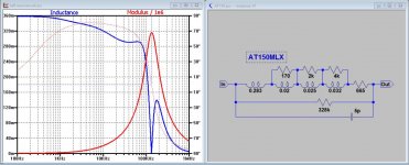
That has some significant problems as the generator properties are very frequency dependant. For example attached is the best model we have at the moment for the AT150 generator. And of course that's only 50% of the system. but nothing wrong with adjusting the frequency response to suit by whatever method floats you boat. I personally have a preference for flat phono stages and sort everything out in DSP. but that is heresey in some circles 😀Actually...if you wanted to go mega-complicated, you could add a microcontroller with a startup routine and a DAC tied to a voltage controlled filter. Verrrrry small voltages into the cartridge/wire to test resistance, inductance, and capacitance, calculate the required filter parameters, and then set the correct voltages for the VCF with a DAC. 100% analog signal path, and now it's universal again.
Attachments
- Home
- Source & Line
- Analogue Source
- Compensating for cartridge response in the phono stage