Hi,
Below is a comparison of various motor structures for subwoofers.

JBL's differential drive wins. Its both coils are overhung and yet produces less distortion, please see Figure 8A on page 7 in attached technote. a) Can anyone tell why?
My guess is that since both the coils are wound opposite to each other on the same pole piece its inductance is nullified (maybe very little remains) as compared to other technologies. In a typical subwoofer the inductance is fairly high due to 4 layer windings and it varies as the voice coil moves in and out, when coil is in the inductance is more and when coil is out the inductance is less. This produces audible distortion. Since differential drive has very less inductance it can firstly go higher in frequency and produce less excursion related distortion. b) Am I making the right conclusion?
Also, the whitepaper states symmetrical field geometry, I dont understand how it helps as ultimately both coils are overhung and will have same non linearity of typical overhung designs. c) Can anyone please explain how symmetric field geometry works to reduce distortion?
If b) is true then it means we could just use multiple small subwoofers instead of 1 big one as the inductance of smaller drivers is less, even if it changes with excursion, the resulting distortion will be higher up in frequency than subwoofer use, hence harmless. d) Do you agree? Of course, XMAX of smaller drivers is less than a bigger one, agreed. For this discussion, let us keep it aside.
Please provide your thoughts for a), b),c) and d).
Attached is technical note of differential drive.
Thanks and Regards,
WonderfulAudio
Below is a comparison of various motor structures for subwoofers.
JBL's differential drive wins. Its both coils are overhung and yet produces less distortion, please see Figure 8A on page 7 in attached technote. a) Can anyone tell why?
My guess is that since both the coils are wound opposite to each other on the same pole piece its inductance is nullified (maybe very little remains) as compared to other technologies. In a typical subwoofer the inductance is fairly high due to 4 layer windings and it varies as the voice coil moves in and out, when coil is in the inductance is more and when coil is out the inductance is less. This produces audible distortion. Since differential drive has very less inductance it can firstly go higher in frequency and produce less excursion related distortion. b) Am I making the right conclusion?
Also, the whitepaper states symmetrical field geometry, I dont understand how it helps as ultimately both coils are overhung and will have same non linearity of typical overhung designs. c) Can anyone please explain how symmetric field geometry works to reduce distortion?
If b) is true then it means we could just use multiple small subwoofers instead of 1 big one as the inductance of smaller drivers is less, even if it changes with excursion, the resulting distortion will be higher up in frequency than subwoofer use, hence harmless. d) Do you agree? Of course, XMAX of smaller drivers is less than a bigger one, agreed. For this discussion, let us keep it aside.
Please provide your thoughts for a), b),c) and d).
Attached is technical note of differential drive.
Thanks and Regards,
WonderfulAudio
Attachments
For the differential drive to "win", it should produce less distortion than single coil woofers, which it does not.JBL's differential drive wins. Its both coils are overhung and yet produces less distortion, please see Figure 8A on page 7 in attached technote. a) Can anyone tell why?
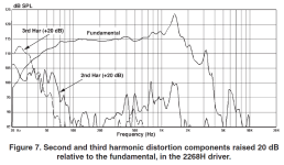
According to figure 7 on page 6, the 2268H driver has 10% third harmonic distortion at 33Hz at ~7.4mm excursion (estimated), and 10% second harmonic distortion at ~25Hz at ~7.3mm excursion.
The drivers impedance is over 20 ohms between 25 to 45Hz.
That distortion was at 23.7 volts, under 30 watts at those frequencies.
That level of low frequency distortion does not appear to be less than a well designed driver with a single overhung voice coil.
The 2268H force factor Bl (X) drops from over 20 to its spec sheet rating of 15 at ~7.5mm, so ~10% distortion would be expected, as it would in any woofer as the coil leaves the magnetic gap.
I can't say your conclusion is right, considering the 2268H distortion is not particularly low at an excursion far under current subwoofer expectations.Since differential drive has very less inductance it can firstly go higher in frequency and produce less excursion related distortion. b) Am I making the right conclusion?
The 2268H's Le is specified as 1.85mH, it's inductance drops more "coil in" than than "coil out".
Art

A) None of those topologies "wins", they each have benefits/drawbacks and each are suited for different use cases. Each of these motor topologies yield low distortion through flat BL curves.
Inductance isn't "nullified" in the differential drive motor. Inductance is probably one of the most misunderstood concepts in motor design. It is more than just the number of winds on a voice coil; the amount of steel in the core and even its saturation level plays a role in a subwoofer's inductance. There is also intrinsic inductance vs. shorted inductance. As an example, you can have a subwoofer with a high intrinsic inductance but a linear Le(x) inductance over stroke which will have low Le distortion but still have a phase angle that moves from capacitive to inductive early which contributes to a steeper inductive rise of impedance. It is possible to have a subwoofer that has linear Le(x) inductance without the use of shorting rings by using very thin pole pieces with a high amount of extension above the gap, or even by using low reluctance materials as the pole. Low inductance is inherent to motors with less coil windings, but motors with magnitudes more windings can have the same low inductance as a result of shorted inductance via shorting rings. Intrinsic inductance is quantified as a ratio of Le/Re. The lower this ratio is, the lower the intrinsic inductance is. B) is not a conclusion for this
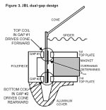
The big drawback of a JBL DD motor is that to produce high excursion, as in the wGTI subwoofers, you essentially have two normal sized overhung coils together on one former which will increase your moving mass substantially. The motor also has to be twice as deep compared to a normal motor with the same amount of excursion. Another drawback is machining and coil spacing production tolerances; both have to be held to a tight tolerance otherwise things become asymmetric real fast C) The symmetrical B fields sum together when both coils are in and near the gap to produce flat BL, with BL falling off once one coil exits the B field. It is essentially the inverse of XBL motors, with XBL having two B fields and one coil instead of one B field and two coils with DD.
XBL and the Aura NRT topologies are both underhung. XBL is technically underhung since the coil height is less than the top plate height. The benefit here is that since your coil is short, you have a lot less moving mass than the LMT or DD overhung designs. The drawback here is that since the coil is short, you are limited on thermal power handling. The way to gain thermal power handling in these topologies is by increasing the coil diameter, but you only gain so much heat radiating area on the coil windings when doing this so power handling does not scale with diameter increase. XBL has another drawback in that machining tolerances are also very important. I have klippel tested a brahma-X brand new from Parts Express, and it has one of the worst BL curves I have ever seen, likely due to gap dimensions that are not properly spaced for its coil height.
The LMT topology is just a standard overhung motor with a coil that has variable winding density to place more windings on the top and bottom edges of the coil to yield more BL at each end of the stroke which creates the flat BL curve. The benefit is that you can transform any traditional overhung motor into a flat BL motor with just a coil change. The drawback is that the coil winding geometry has to be simulated and executed properly based on the gap dimensions and stray flux characteristics of the specific motor it is going in. A LMT coil that might yield a flat BL curve in one motor might not if it is placed in another different motor. Another drawback is the large moving mass from the large coil, and its high intrinsic inductance from the high number of winds if not used with any shorting rings.
Having said all of that, none of these motor topologies are a monolith in characteristics and each one can vary greatly in its BL and inductance based on the design implementation of each one. There are both good and bad examples of each. The only thing common between them is the potential for a flat BL curve; everything else is a variable. For a good read on now each motor non-linearity affects distortion, check out this klippel poster: https://www.klippel.de/fileadmin/kl...rature/Papers/Klippel_Nonlinearity_Poster.pdf
Inductance isn't "nullified" in the differential drive motor. Inductance is probably one of the most misunderstood concepts in motor design. It is more than just the number of winds on a voice coil; the amount of steel in the core and even its saturation level plays a role in a subwoofer's inductance. There is also intrinsic inductance vs. shorted inductance. As an example, you can have a subwoofer with a high intrinsic inductance but a linear Le(x) inductance over stroke which will have low Le distortion but still have a phase angle that moves from capacitive to inductive early which contributes to a steeper inductive rise of impedance. It is possible to have a subwoofer that has linear Le(x) inductance without the use of shorting rings by using very thin pole pieces with a high amount of extension above the gap, or even by using low reluctance materials as the pole. Low inductance is inherent to motors with less coil windings, but motors with magnitudes more windings can have the same low inductance as a result of shorted inductance via shorting rings. Intrinsic inductance is quantified as a ratio of Le/Re. The lower this ratio is, the lower the intrinsic inductance is. B) is not a conclusion for this
The big drawback of a JBL DD motor is that to produce high excursion, as in the wGTI subwoofers, you essentially have two normal sized overhung coils together on one former which will increase your moving mass substantially. The motor also has to be twice as deep compared to a normal motor with the same amount of excursion. Another drawback is machining and coil spacing production tolerances; both have to be held to a tight tolerance otherwise things become asymmetric real fast C) The symmetrical B fields sum together when both coils are in and near the gap to produce flat BL, with BL falling off once one coil exits the B field. It is essentially the inverse of XBL motors, with XBL having two B fields and one coil instead of one B field and two coils with DD.
XBL and the Aura NRT topologies are both underhung. XBL is technically underhung since the coil height is less than the top plate height. The benefit here is that since your coil is short, you have a lot less moving mass than the LMT or DD overhung designs. The drawback here is that since the coil is short, you are limited on thermal power handling. The way to gain thermal power handling in these topologies is by increasing the coil diameter, but you only gain so much heat radiating area on the coil windings when doing this so power handling does not scale with diameter increase. XBL has another drawback in that machining tolerances are also very important. I have klippel tested a brahma-X brand new from Parts Express, and it has one of the worst BL curves I have ever seen, likely due to gap dimensions that are not properly spaced for its coil height.
The LMT topology is just a standard overhung motor with a coil that has variable winding density to place more windings on the top and bottom edges of the coil to yield more BL at each end of the stroke which creates the flat BL curve. The benefit is that you can transform any traditional overhung motor into a flat BL motor with just a coil change. The drawback is that the coil winding geometry has to be simulated and executed properly based on the gap dimensions and stray flux characteristics of the specific motor it is going in. A LMT coil that might yield a flat BL curve in one motor might not if it is placed in another different motor. Another drawback is the large moving mass from the large coil, and its high intrinsic inductance from the high number of winds if not used with any shorting rings.
Having said all of that, none of these motor topologies are a monolith in characteristics and each one can vary greatly in its BL and inductance based on the design implementation of each one. There are both good and bad examples of each. The only thing common between them is the potential for a flat BL curve; everything else is a variable. For a good read on now each motor non-linearity affects distortion, check out this klippel poster: https://www.klippel.de/fileadmin/kl...rature/Papers/Klippel_Nonlinearity_Poster.pdf
Last edited:
Along with the moving mass and the tolerance,The big drawback of a JBL DD motor
DCD Cons - (just brainstorming)
1) the piston dia considering a 3" dia dual VC is reduced for an increased power handling - to cover for the added mass of coils the latest cones are extremely light and very well engineered w.r.t. strength to weight ratio - however when pushed the cone fractures near the neck. Correspondingly a 6inch VC driver takes more punishment prior similar cone failure.
2) production and construction - the production process is more complex than a straight forward 6 inch of 8inch coil.
3) most likely the cooling efficiency will be difficult to match compared to a straight forward 6 inch of 8inch coil resulting in earlier power compression.
4) SFG machining, Inductance stabilizing rings etc more complex
5) Over a period of time the coil centering capability of the suspension system will be reduced and with a long length of vc former - increases likely hood of lower coil rubbing.
DCD Pro
1) Nice name, provides for a lot of marketing firepower
2) Ability to place a braking coil (shorted turn) in -ve movement - this maybe one of the only positives over a conventional SFG motor.
3) If they do - do - a 6inch DCD the power handling will be above the 8.5 inch vc.
My take
Forget all the expensive engineering - go with saturating the magnetic gap in LF - go for the triple or quad stacked large magnet 21inch - 8.5 inch vc drivers. - https://www.alibaba.com/product-detail/Huge-21-Inch-Speakers-8-5_1601374062815.html
Tech has removed the limit of Amp Power - get a 4 to 6.5K amp - light up the driver.
Forget complex woodwork - time consuming production issues - put it in the smallest cab possible all of the process to fab horns for some extra db is done with - add drivers & amp power - use DSP well
adopt - bass boss philosophy - https://www.bassboss.com/catalog/krakatoa-quintuple-18-powered-point-source.
forget hanging rigging line array etc - too troublesome to execute.
if in hifi adopt kef philosophy - https://soundstagesimplifi.com/index.php/equipment-reviews/191-kef-kc62-powered-subwoofer
10" x 10" x 10" , -3db @ 11hz , 105 db
How does an simple overhung motor generate 24mm one way xmax? This is Dayton UMII15-22 Ultimax II 15"
The specs state 24mm Xmax is at 70% BL, meaning the overhung voice coil has partially left the magnetic gap on the forward and back stroke.How does an simple overhung motor generate 24mm one way xmax?
If the promo sketch is accurate, the 76mm diameter voice coil depth appears to be ~45mm, the magnetic gap (top plate) ~8mm.
Using those estimates, 45-8=37/2=18.5mm.
Mechanical Xmax can use more liberal formulas, like adding gap length/4, another 2mm, 22.5mm Xmax.
That's close enough to 24mm for eyeballing a promo sketch.
The sketch also makes it look like the voice coil would have to completely leave the gap before contacting the back plate, though hopefully the suspension would hit it's mechanical limit first.
The specs don't mention Xmech..
Art
The 2269H and 2288H newest version would be a far more comparable driver to NRT's and XBL2 subwoofer with high xmax.I can't say your conclusion is right, considering the 2268H distortion is not particularly low at an excursion far under current subwoofer expectations.
The 2268, 2258, 2272 all have a lot less xmax compared to the other options.
The 2268 and 2258 are exemplary well behaved upwards in frequency compared to the 2269 though, so a tradeoff.
The JBL specs the 2269H at 19mm Xmax, the 2288H at 20mm, both at 1200 watts.The 2269H and 2288H newest version would be a far more comparable driver to NRT's and XBL2 subwoofer with high xmax.
They did cut the VAS from 237 to only 106 for the 2288H.
Probably sounds better having the suspension "hit the brakes" rather than the braking effect when one of the coils enters the other coils gap and is reversed by it's opposing magnetic force.
👍most likely - as braking in case of an opposite energized vc (other than a shorted turn - where the force would be lesser and linear) - will cause rocking motion considering long length length of vc former & force arm.Probably sounds better having the suspension "hit the brakes" rather than the braking effect when one of the coils enters the other coils gap and is reversed by it's opposing magnetic force.
Along with the moving mass and the tolerance,
DCD Cons - (just brainstorming)
1) the piston dia considering a 3" dia dual VC is reduced for an increased power handling - to cover for the added mass of coils the latest cones are extremely light and very well engineered w.r.t. strength to weight ratio - however when pushed the cone fractures near the neck. Correspondingly a 6inch VC driver takes more punishment prior similar cone failure.
2) production and construction - the production process is more complex than a straight forward 6 inch of 8inch coil.
3) most likely the cooling efficiency will be difficult to match compared to a straight forward 6 inch of 8inch coil resulting in earlier power compression.
4) SFG machining, Inductance stabilizing rings etc more complex
5) Over a period of time the coil centering capability of the suspension system will be reduced and with a long length of vc former - increases likely hood of lower coil rubbing.
DCD Pro
1) Nice name, provides for a lot of marketing firepower
2) Ability to place a braking coil (shorted turn) in -ve movement - this maybe one of the only positives over a conventional SFG motor.
3) If they do - do - a 6inch DCD the power handling will be above the 8.5 inch vc.
Attachments
-
JBL - Dynamic Linearity and Power Compression in Moving-Coil Loudspeakers (Mark R. Gander - JB...pdf8.3 MB · Views: 36
-
JBL Differential Drive.pdf332.9 KB · Views: 30
-
jblTECHNOTE3-4 Differential drive.pdf296.4 KB · Views: 33
-
JBL - 2269H - Engineering Design Specification.pdf484.3 KB · Views: 27
-
 2268H_Page_2.jpg126.9 KB · Views: 37
 -
 2268H_Page_3.jpg222.5 KB · Views: 31
 -
 2268H_Page_4.jpg167.9 KB · Views: 28
 -
 2268H_Page_5.jpg153.1 KB · Views: 31
 -
 JBL 2268H at 115dB.PNG72.6 KB · Views: 38
 -
US20050190946A1.pdf1.9 MB · Views: 26
-
US6768806.pdf842 KB · Views: 28
-
 jbl_differential_drive_motor.jpg61.7 KB · Views: 30
 -
DualVoiceCoilDrivers.pdf13.3 KB · Views: 35
-
AuraSound_White_Paper.pdf150 KB · Views: 30
There are 2 versions at least.They did cut the VAS from 237 to only 106 for the 2288H.
2288H (VTX B18)
2288H-M (VTX B28)
- Home
- Loudspeakers
- Subwoofers
- Comparison of various motor structures