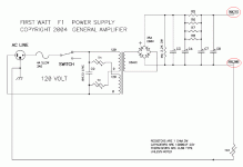
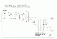
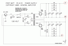
Looking at the F-1 power supply schematic and noticed it was extremely similar to F-5 with one exception:
The F-5 has a run off of the power supply ground, leading to the CL-60, which then goes to chassis ground.
The F-1 appears identical, except each cap bank has its own CL-60 going to ground, and they are not linked as in the F-5.
Can someone explain why this is, or would either amp work either way? I'm sure there is a simple reason I just am not aware of?
Russellc
...... I'm sure there is a simple reason I just am not aware of?
....
exactly
exactly
I will stare at it further. Until osmosis sets in!
Russellc
Last edited:
Oh I get it 1 Bipolar psu as opposed to 2 polar, on the lower channel if i use F1 psu board flip the polarity of the input from transformer flip my filter caps loose one thermistor tie lower + to upper -??? So i have B+ O B-
Dazed and confused , Elwood😕
Dazed and confused , Elwood😕
The F1 has two supply secondaries, isolated through
thermistors so as to absolutely minimize ground loops.
On a good day they measure about 20 uV unweighted
output noise.
😎
thermistors so as to absolutely minimize ground loops.
On a good day they measure about 20 uV unweighted
output noise.
😎
I probably would have figured it out when I went to tie p/s to F5 boards with their V+, GND, V-...
Or not and melted some three legged fuses.
Regards, Elwood😱
Or not and melted some three legged fuses.
Regards, Elwood😱
- Status
- Not open for further replies.
- Home
- Amplifiers
- Pass Labs
- Comparing power supply of F-5 to F-1


