hey,
interesting project..
according to the datasheet of this usb dac it has a hid interface and spdif output. have you considered a second version using the hid interface and/or the spdif?
maybe just add a pinheader for later use?
one more question what pcb program have you used and are there any posibilety for sharing your pcb files??
-emesto-
There is a d-out pin currently, but I didn't put a jumper in to control it! 
But, to answer your question, I am currently drawing up a PCM2707/PCM1794 USB DAC, potentially with selectable inputs for the DAC. This is, of course, not anywhere close to new territory! Russ White has a supposedly excellent solution for this combo already (I only say supposedly because I personally haven't heard it, but I am sure it is high quality!) The point of my new combo will be to drive a set of to-be-built active crossovers/speakers, so I don't think I will put an on-board amp with that DAC.
That being said, I can EASILY modify my current board layout to enable SPDIF output, but that sort of defeats the whole point of having the on-board amp! If you are looking for SPDIF outputs, I would defer to a dedicated USB DAC and not waste the amplifier portion of this project since that adds considerable cost and complexity. Check out the Opus DAC if you are just looking for a USB to SPDIF solution. Also, I have heard GREAT things about Peter Daniel's USB DAC, which you can get information about by e-mailing him directly. Either of these would be better for getting SPDIF.
Finally, I used Dip Trace for the board layouts, and I believe I have posted pretty much everything I have done up to this point! I have found this to be much more intuitive and user friendly than Eagle, plus they have a nice hobbiest version for pretty cheap ($125 I think). Check back through the thread and you should be able to recreate the project pretty easily if you want to make modifications. I will be happy to stick Gerbers of the revised version correcting the minor goofs when I get it finished.
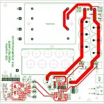
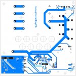
To wrap things up for this project, here is the revised PCB layout to correct a few mistakes. There hasn't been a request for boards since the beginning of this thread, so I am assuming there isn't an interest in a group buy. As such, if anybody wants Gerbers or B&W artwork to make a set of boards for yourself, just e-mail me and I'll be happy to send them along.
I have NOT built this revised board, much less populated it to make sure everything is in fact fixed, so if you want to re-create this project be sure to double check that you know what is what before you start. It should use the same BOM as posted earlier, with the addition of 500 ohm grounding resistors (R27 & R28) which may or may not be necessary depending on whether this input voltage offset is reproducible (I honestly have NO idea what is causing it!) Also, I changed R13 & R14 to 0 ohm resistors.
Regardless, this amp has been running fine for about a week with zero signs of distress, so I'll call it done until it blows up!
Attachments
dfdye said:There hasn't been a request for boards since the beginning of this thread, so I am assuming there isn't an interest in a group buy. As such, if anybody wants Gerbers or B&W artwork to make a set of boards for yourself, just e-mail me and I'll be happy to send them along.
I think that a similar thing could be quite popular as a group buy, if. . . well, there's just two things:
1). To appeal to more people, it would need hole-thru components and the chip attached via socket--or just something considerably easier-looking to solder.
2). You could leave off the power amp so that it could work with a variety of amplifier projects.
One optional device. . . I've noticed several dc blocking caps in the signal path, and, if possible, it would be great if that function could be re-located to the output of the preamplifier, for accomodating personal taste (and a sure-fire way of blocking that dc).
The resulting device, a high quality, easily built, connection from a computer's USB to any amplifier. . . could be more effective than an expensive sound card.
Daniel,
1) Through hole parts made this project too big for my taste, as mentioned in the beginning of this thread.
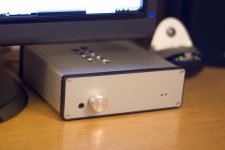
2) The whole point of this project was to have an integrated solution with DAC and amp on one board that fits neatly into a compact case, so leaving off the amp wouldn't serve my design goals.
3) There is ONE cap in each signal from the 2707 to the 2134, not
several, and they are more than sufficient for my needs (Coincidentally, these are the Nichicon ES caps mentioned in another thread). Facilitating multiple cap options (other than those that fit within the reasonable footprint provided) would compromise space considerations. Bypassing is easily achieved on the bottom of the boards by connecting film caps p2p if you really must use them.
4) The "resulting device" you describe has been built and distributed by a number of members of this forum in versions far more refined that what I care to attempt. Look under the "Digital" forum for USB DAC and you will find more options that you can shake a stick at. If you are interested in purchasing such a device, as I have said before in this thread, several DIY kits are offered for sale by Twisted Pear and Peter Daniel to name two. I do not have much interest rehashing something that these guys have already pulled off pretty well.
1) Through hole parts made this project too big for my taste, as mentioned in the beginning of this thread.
2) The whole point of this project was to have an integrated solution with DAC and amp on one board that fits neatly into a compact case, so leaving off the amp wouldn't serve my design goals.
3) There is ONE cap in each signal from the 2707 to the 2134, not
several, and they are more than sufficient for my needs (Coincidentally, these are the Nichicon ES caps mentioned in another thread). Facilitating multiple cap options (other than those that fit within the reasonable footprint provided) would compromise space considerations. Bypassing is easily achieved on the bottom of the boards by connecting film caps p2p if you really must use them.
4) The "resulting device" you describe has been built and distributed by a number of members of this forum in versions far more refined that what I care to attempt. Look under the "Digital" forum for USB DAC and you will find more options that you can shake a stick at. If you are interested in purchasing such a device, as I have said before in this thread, several DIY kits are offered for sale by Twisted Pear and Peter Daniel to name two. I do not have much interest rehashing something that these guys have already pulled off pretty well.
- Status
- This old topic is closed. If you want to reopen this topic, contact a moderator using the "Report Post" button.
- Home
- Amplifiers
- Chip Amps
- Compact USB DAC/Integrated LM1875 Amp