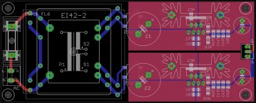
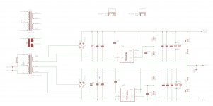
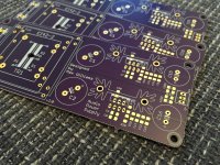
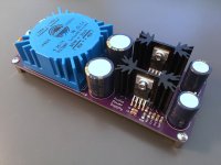
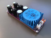
Here is my design for a compact and DIY-friendly power supply using 2x TPS7A3301s to give +/-15V. I want to use for it a preamp but it could also be used for a headphone amp etc.
Currently the BoM looks like this:
TR1 - Block FL6 or FL8, Talema/Amveco 5/7VA or standard EI-42
C1/C2 - Panasonic FK 2200μF 35 V, 18mm
C5/C6 - 1206, 0.1uF, X5R or X7R
C7/C8 - 1206, 47uF, X5R or X7R
C3 - 1206, 1uF, X5R or X7R
C4 - 1206, 10nF/0.01uF, X7R
C9-14 - 1206, 22-15uF
C15/C16 - Panasonic FC 800μF 25 V, 8mm
R1A/B - 1.24M
R2A/B - 105K
B1/2 - VISHAY DFL1508S
I've tried to keep the layout and components as close to the TPS7A3301EVM-061 evaluation module as possible while still making it compact.
Any pointers? Do you guys think the slight layout changes are OK?
Attachments
Hi Maxw,
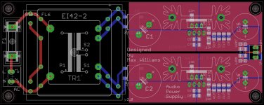
I would suggest to increase top and bottom "Restrict" around the mounting holes at the right side. As it is now it will electrically connect to chassis if metal screws/spacers are used. Your design also needs spacers for the heat sinks which could be avoided if you remove/change some copper pours.
What you've done is similar to Owen's (opc) design in "The Wire" series of boards. His design is even more compact but it does not have on-board transformer.
Regards,
Oleg
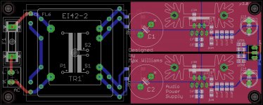
Good idea. Previously I had just relied on the soldermask as insulation. I actually couldn't find an easy way to do this in Eagle so I made a custom part containing a hole and large restrict area.I would suggest to increase top and bottom "Restrict" around the mounting holes at the right side.
I've isolated the heatsinks now. Will also use a thermal shim.Your design also needs spacers for the heat sinks which could be avoided if you remove/change some copper pours.
Yeah I've seen his design but couldn't really see the layout from the photos. I think he had good results and measurements so I'm hopeful for my design too. I think they both follow the datasheet/EVM in components.What you've done is similar to Owen's (opc) design in "The Wire" series of boards. His design is even more compact but it does not have on-board transformer.
Thanks Oleg!
Attachments
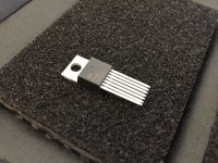
I'm not sure about the pin spacing on the IC though. It looks different between some photos of the EVM.
For example here it looks like the pins are directly underneath the IC, like the pins are straight:
But here it looks like they are bent a lot, like in my layout:
For example here it looks like the pins are directly underneath the IC, like the pins are straight:
An externally hosted image should be here but it was not working when we last tested it.
But here it looks like they are bent a lot, like in my layout:
An externally hosted image should be here but it was not working when we last tested it.
I think the second, where the leads are bent, is the correct pin arrangement. I have these regs still sealed in their bags from Mouser at home but I am on a business trip till the end of the week so can't help right now.
I have undecided what to do with them. I have Owen's PSU board for them and all the other parts but have never assembled it. So I would prefer to keep them until I decide🙂
Last edited:

There's this bit in the data sheet that might explain it 😀
Anyway, nice job Max 🙂
/U.
10.4 Package Mounting
The TO-220 (KC) 7-lead, straight-formed package lead spacing poses a challenge when creating a suitable PCB footprint without bending the leads. Component forming pliers can be used to manually bend the package leads into a 7-lead stagger pattern with increased lead spacing that can be more easily used..
Anyway, nice job Max 🙂
/U.
Ahh I didn't see that. Seems daft to provide the IC in a package that requires manual pin bending!

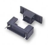
In the future you may consider different fuse holder (see attached example). It hides live contacts from the operator.
Yeah I wanted to do this but I find it really difficult to search through and select parts from websites like Mauser, RS, Farnell etc. There are just a million options, sometimes associated parts are sold separately, sometimes the pictures aren't accurate, you need read a million datasheets. It's just a difficult process so I went with what I used before and that I knew I had the corresponding Eagle part to suit.
Do you have a part number for this?
I have two spare PCBs if anyone is interested. Or if someone wants to make their own, attached are the Eagle layout and schematic files and here is the BoM:
Code:
|  Part name | RS part          | Farnell Part | Mouser Part          | Description                                                     | EVM Part name | Notes                |
| ---------- | ---------------- | ------------ | -------------------- | --------------------------------------------------------------- | ------------- | -------------------- |
| C1/C2      | 571319           |              | 667-EEU-FC1V182S     | Large input cap, 7.5mm/18mm                                     | -             |                      |
| C5/C6      | -                |              | 80-C1206C104K5R      | 1206, 0.1uF, X5R or X7R                                         | -             |                      |
| C7/C8      | 7900610          |              | 81-GRM31CR61H106KA2L | 1206, 47uF, X5R or X7R, 2220 package                            | C1            |                      |
| C3A/B      | 7236657          |              | 81-GRM31MR71H105KA88 | 1206, 1uF, X5R or X7R                                           | C3            | NR/SS                |
| C4A/B      | 2644141          |              | 80-C1206C103K1R      | 1206, 10nF/0.01uF, X5R or X7R                                   | C4            | CFF/CBYP             |
| C9-14      | 7900610          |              | 81-GRM31CR61H106KA2L | 1206, 22-15uF, multiple, 2220 package                           | C5-C9         | Total at least 47uF  |
| C15/C16    | 571408 or 571290 |              | 667-EEU-FC1E102      | Large output cap, 5mm/13mm                                      | C10           |                      |
| R1A/B      |                  |              | 667-ERJ-8ENF1244V    | 1.24M                                                           | R1            | Value for -15VDC     |
| R2A/B      |                  |              | 667-ERJ-8ENF1053V    | 105K                                                            | R2            | Value for -15VDC     |
| B1/2       | 8148800          | 1336500      | 625-DFL1508S-E3/77   | VISHAY - DFL1508S-E3/45, BRIDGE RECTIFIER                       |               |                      |
| IC1/IC2    |                  |              | 595-TPS7A3301KC      | LDO Voltage Regulators -3 to -36V,-1A,Ultra Low Noise,High PSRR |               |                      |
| TR1        | 2239216          |              |                      | Block FL6/FL8, Talema/Amveco 5/7VA or standard EI-42            |               |                      |
| F1         | 7874164          |              | 576-64900001039      | 5x20mm Fuseholder 6.3A 250V                                     |               |                      |
| AC         | 403932           |              |                      | 5.08mm Pitch 2 Way 1 Row Straight PCB Header                    |               | AC in                |
| KK1/KK2    |                  |              | 532-513002B25G       |                                                                 |               | Heatsinks, SK104-PAD |
| LED        | -                | -            | -                    | Any 1206 LED                                                    |               |                      |
| RLED       | -                | -            | -                    | To match LEDs                                                   |               |                      |
| X2         |                  |              |                      |                                                                 |               | Power out            |
| Fuse       |                  |              | 530-5ST63-R          | 5x20mm, 63mA                                                    |               |                      |
Attachments
120 Volt AC Mains Conversion
Your Eagle PCB uses a 240 Volt TR1 Transformer. I need split primary transformer so that I can configure your design for 120 Volt AC Mains.
It looks like this transformer by Nuvotem Talema, Part Number 70033K
would work. It's a 2 x 15 V AC Torodal Transformer that's rated at 7VA with a split dual 115 Volt AC Primaries.
Changing this design means a substitution of the footprint for this transformer
in Eagle. Since I'm need I'm sure I can't undertake this step. Let me know if anyone can help. Take care.😡
Part Number 70033K
would work. It's a 2 x 15 V AC Torodal Transformer that's rated at 7VA with a split dual 115 Volt AC Primaries.
Yes, this is the part I used.
Changing this design means a substitution of the footprint for this transformer
in Eagle. Since I'm need I'm sure I can't undertake this step. Let me know if anyone can help
You just need to change the design to have the primaries in parallel, like you already did for my 5V PSU.
- Status
- Not open for further replies.
- Home
- Amplifiers
- Power Supplies
- Compact DIY friendly dual TPS7A3301 power supply