You can also encase the input transistors + inductors in a mu metal box...
Sure, but properly heat treated mu metal enclosures aren't that readily obtainable and add cost, I would prefer to have an amp that does not rely on them.
With the IPS inductor free I then have the option to add a screen box if I want to make the noise rejection even better.
Perhaps such enclosures are more available in the USA, do you know of a source of shield cans for toroidal transformers?
Best wishes
David
Hi, David!
Some thoughts about CE and CC OPS can be founded here:
http://www.keith-snook.info/wireless-world-magazine/Wireless-World-1995/Ironing out Distortion.pdf
🙂
Some thoughts about CE and CC OPS can be founded here:
http://www.keith-snook.info/wireless-world-magazine/Wireless-World-1995/Ironing out Distortion.pdf
🙂


...about CE and CC OPS can be founded here...
In fact, this was the article that started my interest in the idea, years back when a friend showed me a hard copy.
But it deserves to have a link, thank you
Or you can try that...
Your pictures are hard to read, are they screen shots from a camera?
Or is it just compression, uncompressed format is better.
You need to be careful with stability, your Tian loop probe only captures part of the feedback. There is a direct path back to the JFETs that needs to be included.
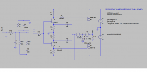
The self-biased JFET input and MOSET common source output is a neat combination but is limited to low rail potential.
If we want more power then there needs to be a cascode or similar to connect the JFET to the outputs.
This is the part I haven't decided on yet.
Best wishes
David
Hi, David!
Some thoughts about CE and CC OPS can be founded here:
http://www.keith-snook.info/wireless-world-magazine/Wireless-World-1995/Ironing out Distortion.pdf
🙂
does anyone have the pdf that they can post it here ? The link no longer works ....
But it deserves to have a link, thank you
You are welcome!
Your pictures are hard to read, are they screen shots from a camera?
Or is it just compression, uncompressed format is better.
Yup, this is just laziness.
I am usung Tapatalk and it provides much more simpler way to post the pics.

You need to be careful with stability, your Tian loop probe only captures part of the feedback. There is a direct path back to the JFETs that needs to be included.
I've captured outside loop and responses of all inserted inner loops must be included automatically.
😉
The self-biased JFET input and MOSET common source output is a neat combination but is limited to low rail potential.
If we want more power then there needs to be a cascode or similar to connect the JFET to the outputs.
This is the part I haven't decided on yet.
K163/J44 are a 40 V pair, but you are clearly right - if more power are needed, than cascode can be applied.
I suppose, that tracking cascode with 2SC3503/2SA1381 must provide huge margin in terms of supply voltage.
😉
does anyone have the pdf that they can post it here ?
https://www.dropbox.com/s/ozpuz5z5rk7s2vd/Ironing out Distortion.pdf?dl=0
Yup, this is just laziness.
The new version is clear but now inconveniently sized.
Somewhere in the middle would be nice.
I've captured outside loop and responses of all inserted inner loops must be included automatically.
This is a common misconception, cause of an almost endless dispute in the Solid State sub-forum.
Your so-called "inner" loop is not truly inner, it intersects with the loop you have checked.
See "Mason' Rule" for gain calculation.
... cascode with 2SC3503/2SA1381...
How would you make it track?
Best wishes
David
Your picture is now conveniently sized, was that moderator action or did I have a forum software problem?
But it looks lousy because it's compressed, use an uncompressed format for clarity.
Last edited:
The new version is clear but now inconveniently sized.
Somewhere in the middle would be nice.
...
Your picture is now conveniently sized, was that moderator action or did I have a forum software problem?
But it looks lousy because it's compressed, use an uncompressed format for clarity.
David, there are three options of size, but in terms of visual representation they are unpredictable:

I have discussed with Tapatalk's team possibility of preview or some kind of visual editing, may be next versions can provide flexible interface for image posting.
 Thank you for proper editing!
This is a common misconception, cause of an almost endless dispute in the Solid State sub-forum.
Your so-called "inner" loop is not truly inner, it intersects with the loop you have checked.
See "Mason' Rule" for gain calculation.
I'm preferring pole-zero interpretation and that schematic are very simple to understand in that way.
So, with similar results i can hope that inner loops can be excluded from analysis in case when they are totally covered by outer loop.
In case of real intersect or complicated overloop we must take care, i agree with that.
But this is a simple case, we doesn't develop Rosetta's Philae landing to the Churyumov-Gerasimenko's comet, doesn't we?
😉


How would you make it track?
Statical style, referenced to the ground:

Tracking style, referenced to the output:

...But this is a simple case, we doesn't develop Rosetta's Philae...
In this case it is as easy to do it accurately as to do it inaccurately, so why not do it the best way?
I suspect that such structures are always as easy to do accurately.
So thank you, the attempt to convince you has made me think some more, whatever it's benefit to you.
If you post the ASC I will show you where I think it should be connected, we can check if it makes much difference.
I will think about the cascode before I comment.
The pictures still look poor, can you not copy the bitmaps from LTspice into Paint and post as PNG?
Best wishes
David
There is surely some problem with the forum software.
Same as yesterday, I look at the thread and pictures are oversized.
I type a reply, return to thread and the pictures are reasonably sized.
Yesterday I wondered if a moderator had altered the pictures but this seems implausible twice.
Last edited:
I will think about the cascode before I comment.
I don't have time to simulate and check, but your output referenced cascode looks like a positive feedback loop.
Stability will depend totally on the combination of the two feedback loops, so the correct technique is essential.
Best wishes
David
If you post the ASC I will show you where I think it should be connected, we can check if it makes much difference.
Let's try, thank you for your kindness!
*cascoded.asc include used 2SK163/2SJ44 and LM7171 models.
The pictures still look poor, can you not copy the bitmaps from LTspice into Paint and post as PNG?
I have entered forum from my laptop instead of usual iPhone and all those pictures are really terrific, i'm sorry.
I don't have time to simulate and check, but your output referenced cascode looks like a positive feedback loop.
Stability will depend totally on the combination of the two feedback loops, so the correct technique is essential.
Yes, that was a stack of bones, some kind of compensation or resistive divider must be applied.
Attachments
Let's try, thank you for your kindness!
*cascoded.asc include used 2SK163/2SJ44 and LM7171 models.
I will try these tonite.
I have entered forum from my laptop instead of usual iPhone and all those pictures are really terrific
After the forum software sizes them correctly they look OK.
But still compression artifacts because they are JPG. PNG is clearer.
Yes, that was a stack of bones, some kind of compensation or resistive divider must be applied.
Actually it is possible to stabilize such a positive loop.
But this is exactly the situation that reveals the problems with your choice of Tian probe placement.
A correct probe placement can analyse this situation.
This extreme sort of analysis was what forced me to work out truly accurate probe placement.
For most ordinary amplifiers it is not very critical.
Best wishes
David
I can't run your ASC because you have not included the LM7171 model.
But I have modified it to show the probe placement.
Ok, the LM7171 was in the other ASC.
Anyway the picture shows the idea.
Attachments
Last edited:
But I have modified it to show the probe placement.
Ok, i've understand what you mean previously.
Mostly the same, still ~100 dB at 10 kHz, just higher UGF.

But this is a good sample when Tian's interception are very different than Middlebrook's interception:

Last edited:
Mostly the same...
Well, fairly major effect on the Unity Loop Gain Frequency, it tripled -approximately.
But the lower frequencies were mostly unaffected because there was not much transmission to the JFET thru the capacitors.
The difference between the true value and the value from the incorrect placement depends entirely on the details of the two loops.
In this case not too bad, but the incorrect placement will never be more accurate than the correct one, could be very inaccurate and you would not know.
So I see no reason to ever do it incorrectly.
...when Tian's interception are very different than Middlebrook's interception:
Similarly, there is no reason to use so-called "Middlebrook", it's never better, may be seriously worse.
Notice the phase error above the ULGF, totally inaccurate for GM, nice example.
Not really fair to call it "Middlebrook", he only analysed it to show it's weakness. I call it "V source"
His own method is much better, now that I understand Tian I have started to work on true Middlebrook GFT.
Best wishes
David
Last edited:
So I see no reason to ever do it incorrectly.
🙂
Of cource, just lazyness and sureness, but only based on knowledge.
Alcohol and experience are often beat youthfullness and fervor...
But there are another and very important question - how much gain inside a loop do we really need?
Similarly, there is no reason to use so-called "Middlebrook", it's never better, may be worse.
David, what about fully-differential version of Tian's intercept?
Say, for example, this:

😉
Or that:

David, what about fully-differential version of Tian's intercept?
I build a "differential to common mode to differential" transformer in LTSpice to do this, it's a mathematical transformer so it works DC to infinity.
I posted it in the Solid State subforum, in a thread I started called "Middlebrook GFT probe" or similar.
A quick search should find it easily.
Use it wisely😉
Best wishes
David
David...
Hi Pavel
You sent a PM but my mailbox was full, just ask here until I have time to empty it.
Best wishes
David
Hi, Dave!
What do you think about modern high-GBW opamps with highly-placed first pole, and even compensated for gains more than 10? Like AD8065, LM7171, THS4021.
Based on pair of this we can create two-opamp composite with OLG at 10x gain like this:

The main goal was to place three poles upper than audioband, so feedback depth stay +- constantly deep up to second harmonic from 20 kHz.
Best regards, Pavel!
What do you think about modern high-GBW opamps with highly-placed first pole, and even compensated for gains more than 10? Like AD8065, LM7171, THS4021.
Based on pair of this we can create two-opamp composite with OLG at 10x gain like this:
The main goal was to place three poles upper than audioband, so feedback depth stay +- constantly deep up to second harmonic from 20 kHz.
Best regards, Pavel!
What do you think about modern high-GBW opamps with highly-placed first pole, and even compensated for gains more than 10? Like AD8065, LM7171, THS4021.
Based on pair of this we can create two-opamp composite
It would be fun to do this as a demonstration of feedback theory.
There was a thread by "Mathias" where he had multiple nested loops to achieve similar loop gain.
Very educational but I believe it's a pointless for a practical amplifier.
A well developed conventional amplifier already has inaudible distortion so there is no improvement in sound, while the extreme circuit has conditional stability that is a potential problem if the amp clips and perhaps as it turns on and off.
Personally I am more interested to use the theory to produce amplifiers that are simple and robust but still achieve very low distortion.
And ideally I would like to improve the efficiency too.
But if you try to build such an extremely fast loop then I would very much like to learn how it works out.
...to place three poles upper than audioband, so feedback depth stay +- constantly deep up to second harmonic from 20 kHz.
I don't think this is necessary, or even desirable as an objective in itself.
Instead, I think that if there is sufficient feedback at 20 kHz to make the distortion very low then it is unnecessary to add even more low frequency gain.
So I am satisfied with flat feedback depth, as an indicator that I have simplified the circuit sufficiently, but I wouldn't complicate a circuit to achieve it.
Best wishes
David
- Status
- Not open for further replies.
- Home
- Amplifiers
- Pass Labs
- Common Emitter OPS?