Yep those are the units.
The thing was they were so different and they just came out of no where.
For a while there Eidetic turned everthing on its head, the dealers spoke highly of the amps and of Greg, he does have the credentials..
macka
The thing was they were so different and they just came out of no where.
For a while there Eidetic turned everthing on its head, the dealers spoke highly of the amps and of Greg, he does have the credentials..
macka
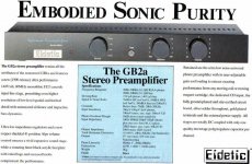
Cheers Macka. I decided to produce the Eidetic amps just after returning from Conneticut certain I could do things a whole lot better than what I was seeing. I might point out that I cut my teeth producing a range of PA amplifiers using the MJ15003/4 back in 1974 similar to the topologies Douglas Self later published.
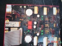
It was in those formative years that I concluded that the main problem with Class AB and the reason so many High End manufacturers turned up their amps to run mostly in Class A with the great size,weight and cost penalty was the half wave currents which radiated/induced a spray of harmonics into the amplifier and I embarked on a path of designing such intrusions out of the amplifier by better inherent PSRR of the amplifier stages, better layout of the PCB to eliminate proximity interactions and great care with wiring looms to eliminate stray fields. For example all supply wiring to the output stages was twisted together and run perpendicularly away from the board connection point to the central power supply.
This is how I managed to get the vanishingly low THDs and -90dB crosstalk at 20KHz from a common supply (full capacitor bank for both channels).
Once any vestige of that harmonic spray was gone there was an enormous soundstage, air and focus. So much low level detail waiting to be uncovered.
That's when I started doing the CD and DAC CHIP and Class A upgrades as well because the difference was glaringly obvious. People who had purchased the amps wanted a better CD source to take advantage of the higher resolution.
AG,
could you enlighten us Euro ignorants by telling what the Greg Ball 1A and 1B were.
I just read your words as that high class A biasing was preferred then due to ill board design and powerlining ?
My doctor girlfriend has a photographic memory, i'll remember to call her Eidetic this evening.
could you enlighten us Euro ignorants by telling what the Greg Ball 1A and 1B were.
I just read your words as that high class A biasing was preferred then due to ill board design and powerlining ?
My doctor girlfriend has a photographic memory, i'll remember to call her Eidetic this evening.
Hi Jacco,
The earlier models you ask about were using LF357 (x10 decompensated LF356) chips and LM317/337 regulators. The newer ,prettier models substituted OPA627/637 chips and Linear Tech regulators. Really a cosmetic upgrade and a chip update to the newest technology. I probably had the first commercial audio products with the OPA chips anywhere!
The OPA627/637 have a monolithilic matched FET cascode input stage, superior PSRR and great slewing rate and the audible difference my wife and I heard dictated that the change had to happen despite the high price from Burr Brown. They were delivered to Australia especially for us. The same happened with MJ15003/4 which were delivered directly to us from Motorola HQ in 1974.
You're not ignorant. Feedbach theory dictates that the more gain introduced before the point of Power Supply intrusion the greater the isolation. So I honed it by placing the high gain chips before the symmetrical Vas. Try rolling a discrete front end better than that in an OPA627. And it came with an offset trim so I didn't need a servo as the tracking is near perfect.
Hi all !
Normal music program does not contain high average power.
(Except you are designing a instrumental amp for a bass guitar
or similar..... )
)
Let's consider music a program that contains max signal with a magnitude of 50 V. The amp must be able to deliver this without clipping. into 8 Ohms a 50V (peak of sine wave) output would make over 150W.
In fact the related music signal is usually by far below this level.
According my measurements, I would expect an average power content of such a music signal around 30W or even less.
To evaluate if the amp is matching to your requirements, you would need to apply your typical music. ....put the volume to the level
which the amp can deliver without clipping.... and see if this condition is thermally fine....
In general I would guess that a stiff power supply that can deal with high power for some seconds is necessary.
But the thermal management does not need to be designed for 150W continuous power.
Looks like a perfect match for a light weight regulated SMPS.
I am right now trying this approach for my subwoofer.
I am curious if this concept will work in a satisfying way.
....time will tell.....
Bye
Markus
Normal music program does not contain high average power.
(Except you are designing a instrumental amp for a bass guitar
or similar.....
)Let's consider music a program that contains max signal with a magnitude of 50 V. The amp must be able to deliver this without clipping. into 8 Ohms a 50V (peak of sine wave) output would make over 150W.
In fact the related music signal is usually by far below this level.
According my measurements, I would expect an average power content of such a music signal around 30W or even less.
To evaluate if the amp is matching to your requirements, you would need to apply your typical music. ....put the volume to the level
which the amp can deliver without clipping.... and see if this condition is thermally fine....
In general I would guess that a stiff power supply that can deal with high power for some seconds is necessary.
But the thermal management does not need to be designed for 150W continuous power.
Looks like a perfect match for a light weight regulated SMPS.
I am right now trying this approach for my subwoofer.
I am curious if this concept will work in a satisfying way.
....time will tell.....
Bye
Markus
From all this it is fairly obvious that a toroid of equal to the amps 2 channel power rating is adequate and I have never had one fail! Of course, it will sag under demand but so what? Also the capacitor bank only needs to reduce ripple to a manageable level of say 1V at full power. From Q=CV and with 50Hz AC that means 18,000uF per 100W 8ohm channel.
The resulting amp will have a soft supply but great dynamic power the equal of a much larger amp but with lower cost and dissipation.
The resulting amp will have a soft supply but great dynamic power the equal of a much larger amp but with lower cost and dissipation.
I think it has been remarked on more than one ocassion that the "soggy power supply" phenomonon was one of the (if not "the") inspirations for Carver's early amps like the M-400. Anyway it certainly make sense when building a commercial product not to design more capability than will ever be used.
For a DIY amp there are some sensible reasons for "overbuilding":
A- we don't build very many units and thus lack the practical experience of a commercial operation, therefore an overly conservative approach gives a greater margin for error.
B-Due to lesser experience and/or minimal equipment we spend more time pumping full power sine wave through an amp while scratching our heads in puzzelment - bigger transformers and heatsinks let us get away with this.
C- We are seduced by the "coolness factor" into desiring the baddest amp on the block, not at all unrelated to lusting after a 350hp Mustang convertable rather than a Prius (bad example as appearently Priuses are geek/nerd magnets).
D-Since we can't buy components in large volumes the materials often cost us more and the incremental cost of 25-50% more VA or capacitance doesn't really impact the overall cost that much anyway.
Sam9
Good points all. I tend to produce amps for commercial realisation and hone them for best performance/value from that perspective. Time spent on finessing PCB geography and chassis layout/lead dress on instruments is worth it but an out of reach option for DIYers. You'd be surprised the companies that don't even know to bother - preferring to market their poor figures as Black Art or fall back on Class A as safe refuge.
Unfortunately the ultimate extension of your intimations are Class A overbuilt, oversive, overcostly and to an environmentalist, over consumptive. Without even touching on the subject of those with undersize append....
There just something about a finely honed Class AB without any downside. BEAUTIFUL.
To amplifierguru : As I see, you are not " blind " fan of class A. Well, me too 😉 . Can you show some your work ?
@Guru:
yepp, your rule of thumb for a traditional trafo/rectifier/capacitor design is matching more or less to my view.
I am glad to see a professional, who designes high quality without
unsaint giant torroids.
@ Sam:
From my perception 18.000 uF for 100W/ Ohms is not so soggy. Even if we estimate 2V discharge drop a lowest frequencies and another 2...3V drop due to the impedance of the transformer. 4...5V worst case rail drop are not really soggy for a +/-50V supply (+/-50 V might match to a reasonable 100W/8 Ohm design.) ....have seen MUCH worse...!!!
Cheers Markus
Yes ChocoHolic,
Nothing wrong with a supply that sags. You simply start with a higher voltage and accept that. The big advantage is lower cost of supply toroid, weight, size and of course the power's not lost - it's still there as dynamic headroom. In the example unit 240Watts at clipping from a 300 VA two channel supply!!
Of course the design topology MUST be tolerant of supply variations without intrusion but to the informed that's easy.
Added a picture of the German AVM Evo M3 pcb.
(OPA627 near the Neutrik, the man loved trace bridges)
The original, the M1, started as a diy design, from an article series in the German magazine Stereoplay in 1987-1988.
With a 160VA toroid the amplifier was tested at 100/180/260 in 8/4/2 Ohm.
Admitted, the PS was layed out for 0.25V ripple at 150 watts in 4 Ohm.
I can not imagine a single M1 owner complaining over lack of dynamic headroom.
The original design employed an 5534, 4 RCA Mosfets in the output stage.
(BC414/416-BC546/556-BD139/140-Drivers: BD139/140 inbetween)
The commercial units later received the OPA627 in late 92, the output changed over to 6 IRF Mosfets.
I switched the ones i built to OPA627's in April 1991, paid $60 for an OPA627 and minimum order was 10 pieces.
Reading the article on the M3 with OPA627's a few years later was no surprise.
Forgive me Father, i have sinned !
In 1988 i spoke to the designer/owner of AVM, Gunther Mania, on the phone a couple of times.
I asked him if there was a possibility of converting the design to class A by lowering the PS voltage from 40vdc to 30vdc, retain the 40vdc PS for the front stage, and enlarge the size of the PS and Heatsinks.
Both the 100 watt AB and 50 watt class A version i enjoyed very much.
To my surprise AVM not only came out with the M3 in 1992, also with the 40 watts Class A M4 !!!
(i have only asked audio designers silly questions since)
Attachments
I think, the suitful limit for supply sagging is also limited by
the required no load voltage. If you really have massive
sagging, then the high supply voltage will cause higher idle losses
and high voltage transistors without enabling high output power.
My 8x150W (2 times 4x150) oldy has quite massive torroids, but the caps are not that fat, - unfortunately...
For each quadruple amp bank of 4x150W, there is a 1kVA torroid (680 VA might be enough) and 2x50 000 uF ( no luxury for 600W). At no load condition the rails are +/-56V. When running all amps with full power at the same time, then the rails are sagging so heavy (around 42V if I remember right) that 35Vpeak output voltage is already the limit for clipping !!
(Well I got these 65V / 50000 uF caps for around USD 1,- from a recycling center..... and already the 4 pieces consumed all the space, which I was willing to spend.....)
Well that old amp is far from perfect, but is still working for my current subwoofer.
- Status
- Not open for further replies.
- Home
- Amplifiers
- Solid State
- Commercial Product