Hi,
Whilst at work - doing sod all...I had an idea for a crossover (probably not a new one!).
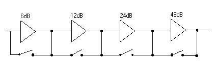
I would build up a 48dB active xover (or more) with a relay aound each one. Before those could be a gyrator with a xover around it.
By energising the relays, you would bypass the crossover, so that by engergising all of them would be staright-though. By energising three, you would get a 6dB rolloff and so on. By energising 3 and not the gyrator, you would get an 'infinite slope xover'.
I have included a quick pic (minus the gyrator)...
What do you think? / Comments?
Gaz
Whilst at work - doing sod all...I had an idea for a crossover (probably not a new one!).
I would build up a 48dB active xover (or more) with a relay aound each one. Before those could be a gyrator with a xover around it.
By energising the relays, you would bypass the crossover, so that by engergising all of them would be staright-though. By energising three, you would get a 6dB rolloff and so on. By energising 3 and not the gyrator, you would get an 'infinite slope xover'.
I have included a quick pic (minus the gyrator)...
What do you think? / Comments?
Gaz
Attachments
Sorry, this is a nice try but you can't do this (if you want a Bessel, Butterworth, Tjebusjev, L-R). Why?
Each part will have different corner frequenceis for different "orders".
If you do the filter in this way the filter become very "soft", no sharp at all except for frequencies far far away.
But, not to scare you off, if you at the same time can tune the frequencies then it will work. But what about the frequencies? I have fat book in the subject but somebody else can maybe help you digging up the filter coefficients.
Forget to mention that you must build the filters in "pairs"(12dB) plus a single one (6dB). You can't get Q (resonance) high enough otherwise.
Make a 48db crossover
Make a 24db crossover
Make a 12db crossover
Make a 6db crossover
By now you have a huge circuit board - hehe
How connect the relays
Make a 48db crossover output --> relay
Make a 24db crossover output --> relay
Make a 12db crossover output --> relay
Make a 6db crossover output --> relay
LOL
Make a 24db crossover
Make a 12db crossover
Make a 6db crossover
By now you have a huge circuit board - hehe
How connect the relays
Make a 48db crossover output --> relay
Make a 24db crossover output --> relay
Make a 12db crossover output --> relay
Make a 6db crossover output --> relay
LOL
Hi,
I haven't gotten around to modelling it yet...I'll let you know when I do. It was my understanding from past experience and ESP's Linkwitz-Riley Crossover Calculator that to make a 12dB you use one section then to make a 24dB you use a two stage byt cut and pasting the circuit on the end. Component values are the same. I made a mistake before by saying 6dB as the first stage, it should be:
12dB 24dB 48dB 96dB(?!)
To tune the frequencie's I would use a digital potentiomenter by Maxim/Dallas. I do not trust their values - rather I work out each step frequency I want, and work out the appropriate resistance to get out of them. By having two in parallel, you can get very accurate results.
Gaz
Peranders is right
Forget to mention that you must build the filters in "pairs"(12dB) plus a single one (6dB). You can't get Q (resonance) high enough otherwise. active filter design is not for beginers.
This is why the Pass labs has a Q adustment for each 2nd order section. Go look at:
http://www.passlabs.com/pdf/XVR1MAN1.PDF
http://www.rane.com/note119.html
http://www.crossovers.com/index001.html
http://www.linkwitzlab.com/filters.htm
http://www.marchandelec.com/xm16.htm
H.H.
Mental Note: Remember to chuck Electronics Degree in the bin?!
If these changes are variable resistors then one could work out their value (even by listening) and programme them into the microprocessor that would control the system (a PIC16F877 in my case). If the whole system was variable to the PIC then it could work? Is it worth the bother?!
If these changes are variable resistors then one could work out their value (even by listening) and programme them into the microprocessor that would control the system (a PIC16F877 in my case). If the whole system was variable to the PIC then it could work? Is it worth the bother?!
--It was my understanding from past experience and ESP's
--Linkwitz-Riley Crossover Calculator that to make a 12dB you
--use one section then to make a 24dB you use a two stage by
--cut and pasting the circuit on the end.
That is what is shown here (see link...witz .... pun intended).
There is no reason why you can use a a relay to "pick" the output
you desire, but your phasing will be different depending
on which one is selected - hehe You could add additional circuits like a "phase correcting buffer" to fix this.
http://www.linkwitzlab.com/filters.htm#2
- Status
- Not open for further replies.
- Home
- Amplifiers
- Solid State
- Comments on Variable Slope Crossover?