Kari,
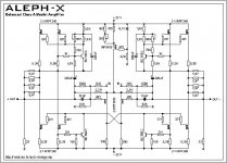
Sorry, I looked right past it. Thank you for pointing it out. Do you have a copy of Kristjan's schematic you could post? His web site is down. I don't know if it is down forever or if his ISP is just down.
Sorry, I looked right past it. Thank you for pointing it out. Do you have a copy of Kristjan's schematic you could post? His web site is down. I don't know if it is down forever or if his ISP is just down.
Kari,
Sorry to be a pain but what pitch did you use for the main board outputs to the driver boards and css boards so we can pick out terminal blocks. Same question for the driver boards. Lastly are the electrolytics 5mm pitch?
Sorry to be a pain but what pitch did you use for the main board outputs to the driver boards and css boards so we can pick out terminal blocks. Same question for the driver boards. Lastly are the electrolytics 5mm pitch?
Hi Kari!
Thanks first for taking this effort!
Will you also accept € for payment, it would be easier for many other Europeans (dutch... )
Best wishes😉
Thanks first for taking this effort!
Will you also accept € for payment, it would be easier for many other Europeans (dutch... )
Best wishes😉
Thank you, Gogo, for the schematic. Dobbeln, I will chime in with you in saying Kari has done a wonderful job designing the boards and has really taken it over the top by offering the group buy. Many thanks to you Kari. In a couple days the price should be set and we will be able to pay for them. The boards will look great with the red solder mask. I can't wait to get them. I am like a kid in a candy store.
You are welcome, Kilowattski!
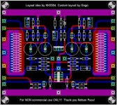
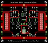
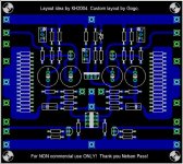
My implementation of Kari`s layout will be ready soon. I use Eagle 4.13. The layout will be similar, but with some minor changes (according to my local source of components). I will post the layout (in JPG, or Eagle PCB-format, or Gerber) so anybody can make the boards as I wanted.
Regards
My implementation of Kari`s layout will be ready soon. I use Eagle 4.13. The layout will be similar, but with some minor changes (according to my local source of components). I will post the layout (in JPG, or Eagle PCB-format, or Gerber) so anybody can make the boards as I wanted.
Regards
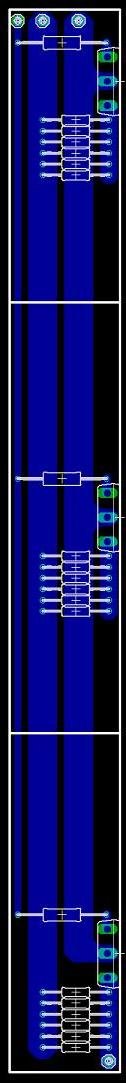
My only comments are that the components should be marked with a R or C or Q number to make assembly easier. The outputs to the CSS and driver boards need to be evenly spaced and be set at a standard pitch for a terminal block to be implemented. Also the output .47 ohm resistors are usually 3 watt types. That being said you need 48 resistors on each side not the 16 you have. I recommend you go back to the layout for 4 power resistors with a 1" pitch. Mills MRA-5 resistors work quite nicely there. Overall I like it. I will use the Gerbers to make a spare board with a PCB Router I have access to. Thanks for your efforts.
The caps on the board has a 5mm pitch and the outline of it is 16mm in diameter. I'm planning on using Elna Cerafine 220uF/35V. However i have at this point planned on soldering wires directly to the board and not at all use a terminalblock. I'm also redisgning the driver/ccs board as i'm not happy with the current layout.
/Kari
/Kari
Kari,
Would it be too much trouple to make the output pads for the CSS and driver boards a standard pitch for a terminal block the same for the CSS and driver boards? It just make assembly and connection a snap when tweaking or relacing a transistor instead of soldering and resoldering the PCB in and out. Eventually the PCB trace will lift up even with a well made board after repeated soldering and desoldering.The same could even be done for the xlr input. Just a suggestion.
Would it be too much trouple to make the output pads for the CSS and driver boards a standard pitch for a terminal block the same for the CSS and driver boards? It just make assembly and connection a snap when tweaking or relacing a transistor instead of soldering and resoldering the PCB in and out. Eventually the PCB trace will lift up even with a well made board after repeated soldering and desoldering.The same could even be done for the xlr input. Just a suggestion.
Well Kilowattski,
I allways preffer to use solder-joints instead terminal block, so I dont care about the spacing. About resistors - I will use 0,6W/2 Ohm 1% metalfilm, this is about 2,4W per resistor block, I think that will be enough. I have a marking for the components, but because locations are the same as the Kari board, I have removed the components marks for clarity.
>>>Overall I like it. I will use the Gerbers to make a spare board with a PCB Router I have access to.
Did you mean that you want the files for my implementation of Kari`s design?
Gogo,
Thank you for the offer, but I think I will pass. This is very much a tweakers amp. Effort to minimize dc offset will be required as well as other tweaks to get the amp just right. I don't want to be soldering and unsoldering the wires from the CSS and driver boards every time I want to make a simple resistor change. If one was concearned about soldering directly to the board, a terminal block could be soldered in temporarily until all tweaks are make and then permanently soldering the wires to the board. That would mean solder, unsolder and resolder only once, but the board needs to layed out for ternminal blocks.
Thank you for the offer, but I think I will pass. This is very much a tweakers amp. Effort to minimize dc offset will be required as well as other tweaks to get the amp just right. I don't want to be soldering and unsoldering the wires from the CSS and driver boards every time I want to make a simple resistor change. If one was concearned about soldering directly to the board, a terminal block could be soldered in temporarily until all tweaks are make and then permanently soldering the wires to the board. That would mean solder, unsolder and resolder only once, but the board needs to layed out for ternminal blocks.
I'm drawing a new ccs/driver board as i write this. It will feature both terminalblocks (7.5mm pitch) and solderpads. Size is going to be 100mm x 50mm. I'll post pics as soon as i'm done so ppl can approve the design, because of the deadline for the groupbuy.
Also i expect to get the pricing information tomorrow, at the latest on Friday.
Thx,
Kari
Also i expect to get the pricing information tomorrow, at the latest on Friday.
Thx,
Kari

Is is too late for me to bump my numbers from 2/8 to 4/16? A guy at work might be interested but did not find out until today about it. If not, its not a big deal. Just let me know
Howie
Howie
Hello Kari, I missed the Wiki deadline for this group buy. If you happen to have some spares I would like 2 main PCB's and 8 CCS PCB's. I can Pay Pal you if you have them.
Regards
Anthony
Regards
Anthony
- Status
- Not open for further replies.
- Home
- Amplifiers
- Pass Labs
- Comments on my Aleph-X layout?