OnAudio,
In short it would be like trying different tires on my Bentley to establish which offers the best road holding road noise and braking performance each rated 1 - 10 - does it make sense?
Hi Nico,
I get you. However you might be surprised at what a modern PC can do compared to a modern Mac.
It depends what your objectives are and what the criteria is on choosing a product, which also depends on how they market it.
Funny how basic spice simulations don't tell you much beyond the chip - even the manufacturers models, mostly power transistors, are unreliable in many cases, as we read here often.
People who assure you that their sims will work as predicted are not telling you how much experience with the parts, circuits, data and models they have to back such a bold claim. Until then, its design, build, test and then maybe listen.
There is no cred. here for marketing-hyped specs. - no one is buying anything.
Last edited:
Hi Ian,
I cannot imagine why a company who's livelihood depends on manufacturing components for inclusion into products can afford providing bad information. Are you suggesting that no products actually works.
You as a user could change a data sheet if you feel that you know better than the manufacturer. Do not be surprised that a component manufactured by On-Semi with the same part number preforms radically different from one made by Philips. That is why an engineer in a manufacturing environment would specify that they use a BC556C manufactured by Philips for instance, is the only component to be used in the design.
The problem is that hobbyists buy components from vendors specifying little other than the part number and could end with a mixed batch of various manufacturers all performing differently. Thus use the datasheet from the manufacturer of the part you intend using.
Hi Nico - 'no problem at all with your synopsis of component data. The issue, as the thread reveals, is an over-reliance on simulation and perhaps unreliable spice models, often commented on. It is well known how poor On-Semi's (of all manufacturers) free spice models can be. I refer to Bob Cordell's site for an indication of the large number of power semi spice models that required revision for his purposes. It's a worthy subject covered also in his book thread but I'm sure you would have doubts anyway, about the audio power reliably available from a single pair of T03 darlingtons, whoever made them. I assume we are not considering PMP or pulse testing as a basis for audio power claims, however.
I often see in recent up-market amp. specs that amplifier X claims simplistically derived figures like 100W into 8 ohms, 200 into 4 ohms and 400W into 2 ohms. Unless the laws of physics have finally been overcome or the amplifier increases its gain to counter the increasing losses, we would recognize this as imaginative hype. I think that power amplifier designs posted here should show reasonable regard to component package limits, feasible heatsinking and SOA limitations, or at least an admissiont to a lack of understanding. If not, what consideration do any claims deserve? 🙄
It's certainly possible to do thermal modelling in design simulation but few indicate or discuss it and most "sims" are performed largely on small signal lines. In this case, we should at least use the manufacturer's data to scale the power stages, showing due allowance for current and dissipation, whether we are amateur or pro.
I'm quite sure you don't need the lecture, though. 🙂
Of course you are correct. But it is like everything else - if you don't complain to the manufacturer nothing changes. We do this all the time we go to a restaurant don't enjoy the food and never go back. Instead we should make the manufacturer aware that he cocked up his data, he can only thank you for it.
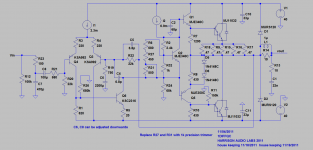
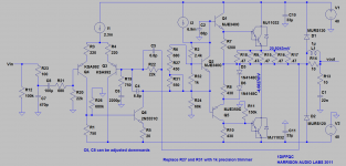
Note: 2N5551C,MJE340C,MJE350C,1N4148C are actually 2N5551, MJE340, MJE350, 1N4148. The C stand for a Cordell Model 😉. Well there is a lot you could do with C6 and C8. If you don't want to replace them after every 3 years you could go polyester or tantalum(with care). Your power supply capacitors will most likely have around 3000 hours.
Attachments
30k plus builders wanted
Feedback needed on your experiences with this amplifier. Contribute to the state of the art. Build and feedback.
Feedback needed on your experiences with this amplifier. Contribute to the state of the art. Build and feedback.
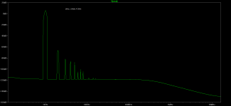
Following request on how current sources look like check post #29 here http://www.diyaudio.com/forums/solid-state/199196-new-dawn-1diffqc-amplifier-3.html
Thanks.
Thanks.
Feedback needed on your experiences with this amplifier. Contribute to the state of the art. Build and feedback.
Hi Harrison,
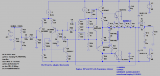
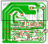
This is my simple inexperianced layout. Just trying to learn the art of pcb design. The output coil will be at speaker terminal.
Regards,
Attachments
thank you for responding to the call
I see passion in your work. Very nice. Just a few comments.
1. You could consider moving zobel to speaker side.
2. The negative rail is feeding one of the big boys before it gets to the other boys. The capacitor fix you put may be ok.
3. I took a quick look 😉
All the best
I see passion in your work. Very nice. Just a few comments.
1. You could consider moving zobel to speaker side.
2. The negative rail is feeding one of the big boys before it gets to the other boys. The capacitor fix you put may be ok.
3. I took a quick look 😉
All the best
Hi RSK,
I had a chance to go over your layout again over the weekend. The high lighted capacitor is converting our quiet ground into a high current ground. Also the quiet ground is not clearly demarcated. While this might not cause problems in operation I thought it prudent to point it out.
kind regards,
Harrison.
Attachments
Hi RSK,
I had a chance to go over your layout again over the weekend. The high lighted capacitor is converting our quiet ground into a high current ground. Also the quiet ground is not clearly demarcated. While this might not cause problems in operation I thought it prudent to point it out.
kind regards,
Harrison.
Hi Harrison,
Thank you for your concern.
Please show me how to get it right.
Kind regards.
Hi RSK,
Use a star ground system. Rail decoupling capacitors normally connect to high current Ground. Ground connections around the input transistors could be considered low current ground. Let all ground connections return to one star point that is properly decoupled.😉
kind regards,
Harrison.
Use a star ground system. Rail decoupling capacitors normally connect to high current Ground. Ground connections around the input transistors could be considered low current ground. Let all ground connections return to one star point that is properly decoupled.😉
kind regards,
Harrison.
Hi RSK,
Use a star ground system. Rail decoupling capacitors normally connect to high current Ground. Ground connections around the input transistors could be considered low current ground. Let all ground connections return to one star point that is properly decoupled.😉
kind regards,
Harrison.
Hi Harrison,
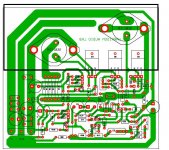
Hope this is good. Changed pins for A992 transistors that I have.
Regards.
Attachments
Hi RSK,
Thats much better. The Ground system is now much more defined. Lucky you, you got those input transistors 😉. Looking forward to those listening tests.
Cheers 😉
Thats much better. The Ground system is now much more defined. Lucky you, you got those input transistors 😉. Looking forward to those listening tests.
Cheers 😉
OnAudio, are you going to take your amp further, for example a builders thread, or will it end here? I vote that it has the potential to be a nice group project.
I'm still trying to figure out what's the "magic juju" in this schematic 😉 I can't find anything noteworthy that would be the result of an "applied formula". The only thing a lil different are the staged reference voltages for the CCS' but beyond that..
Hi Michael, no this is a standard darlington configuration used in a TEF. The difference is this transistor is one of the thougher cookies in the jar and well suited for high current drive and DC motor control. It would mimic on quick guess 6 x MJ15003 paralel connected output devices crammed into a single package making matching unnecessary. It could contribute much of the output character of the amplifier relating to brute force and very low output impedance, However it is by far no magical formula for success.
Ladies and gentlemen I am still waiting, kindly jump in and experience something different 😉 This amplifier uses a smaller board size 😉
The closest finished project should be that of RSK.....also waiting.
- Status
- Not open for further replies.
- Home
- Vendor's Bazaar
- Combined Onaudio thread. (23 threads)