I have a question regarding a combination of choke and line output transformer loading for preamp tube and I'd appreciate your answers.
I'd like to use a line output transformer for loading of my 01A tube preamp. The output transformer has only around 90H of primary inductance which I believe is a little short for loading 01A tube at low frequency.
Is it possible that I'd use an additional 50H choke (audio choke) in serie with the primary of the line output transformer, according to my understanding:
If I take the output at the anode of the 01A tube (via a capacitor), it should be Ok since in this case the primary of the line output transformer will act like a choke in serie with 50H choke (the secondary will be left un used), so total inductance of the two will be 140H and the low frequency will be improved albeit with high output impedance.
If I take the output at the secondary of the output transformer, I believe the output will be lower than before since there will be a voltage divider between the choke and the primary of the line ouput transformer, that's acceptable for me but my main concern is would the low frequency at the ouput of the line output transformer improved or not?
If you have a plate choke from B+ to plate, a coupling cap (we'll assume it's a big coupling cap) connecting your OT from plate to ground, then one end of the choke and one end of the output transformer are both at AC ground and the other end of the OT and plate choke is connected to the plate. This isn't a series connection, it's a parallel connection.
A 50H plate choke is going to be a tremendously limiting component here. That's ~6K at 20Hz for a tube with an Rp of ~10K. It doesn't matter what coupling cap and line output transformer you use, the load will always be less than the reactive impedance of the plate choke. IMO, you can't realistically use a plate choke to load an 01A, as you'd need 300H. A CCS works just fine though!
A 50H plate choke is going to be a tremendously limiting component here. That's ~6K at 20Hz for a tube with an Rp of ~10K. It doesn't matter what coupling cap and line output transformer you use, the load will always be less than the reactive impedance of the plate choke. IMO, you can't realistically use a plate choke to load an 01A, as you'd need 300H. A CCS works just fine though!
I understood ncc different, as in: anode - choke - primary of the line transformer - ground, and than taking the signal form the plate with a coupling capacitor.
Still not enough Henry according to your calculation.
Correction: "ground" must be "B+", else the tube doesn't have a dc-path.
Still not enough Henry according to your calculation.
Correction: "ground" must be "B+", else the tube doesn't have a dc-path.
Last edited:
Ah, I think I am understanding now.
Yes, you are going to lose output with the primary of the line out transformer and the choke in series. You'll still have poor loading at low frequencies. Transformer coupling the output of an 01A isn't the greatest idea.
Yes, you are going to lose output with the primary of the line out transformer and the choke in series. You'll still have poor loading at low frequencies. Transformer coupling the output of an 01A isn't the greatest idea.
Thanks you all for the replies!
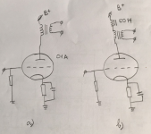
To make my idea clearly understood, I attached the schematic below.
1/ Case a:
This is what i'm using at the moment. According the inductive reactance calculator:
Inductive Reactance Calculator • 66pacific.com
90H of the primary of the line out trans is equivalent to 11,310 ohms @20hz which is more or less the same as the plate resistance of the 01A tube, that's why the low frequency response of the preamp is not so great
2/ Case b:
If I connect a 50H choke in serie with the line out trans primary then the total henry of the two will be 140H and is equivalent to 17,593 ohms @20hz
- If I take the output at the plate of the 01A tube (via a capacitor) instead of the secondary of the output transformer (the secondary of the output transformer will be left unconnected) the the tube will be loaded by an equivalent choke of 140H and the frequency response of the output will be better (abeit with higher output impedance, which is not so great for preamp)
- How about If I take the output at the secondary of the output transformer? I know that the output voltage will be much lower than in case a due to voltage divider between the choke and the output transformer primary and that's acceptable for me but how about the low frequency response of the output? is it better than case a or not?
Thank you!
Attachments
A 90H transformer and a 50H choke:
At the low bass limit the '01's signal is split as 36/64. If you only take signal from the transformer, the choke is robbing some of your signal.
Midband, load on the transformer, the choke robs ALL your signal. It is, as it appears, a "high-cut" working from about the botton of the audio band. Exactly like a series choke on a woofer.
Attachments
Distortion will also rise significantly as well.Thanks you all for the replies!
90H of the primary of the line out trans is equivalent to 11,310 ohms @20hz which is more or less the same as the plate resistance of the 01A tube, that's why the low frequency response of the preamp is not so great
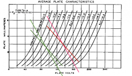
Plotting the load line for the two data sheet operating points with Xl at 20Hz. gives not much slope change between the two inductances but small differences sometimes make worthwhile impressions . . . . .
If you've got the choke there your idea is worth a try, no?
If you've got the choke there your idea is worth a try, no?
Attachments
IMO, you can't realistically use a plate choke to load an 01A, as you'd need 300H. A CCS works just fine though!
Of course you can use a plate choke to load an 01A! A standard Lundahl LL1667 gapped for 15mA will give you 270H. If you order it with a smaller gap the inductance will be much higher. I have a pair of LL1667s that I intend to use with the 01A. They are gapped for 5mA. That’s 800H!
I suspect that 800H will not be a problem.
But . . .
The distributed capacitance may, or may not, roll off the response at 10kHz or 20kHz.
It is a case of 01A rp, versus Xc at high frequencies.
My book shows 01A rp = 10k Ohms.
If the transformer capacitance is not rated, then just a simple frequency response test will reveal if there is any problem or not.
Last edited:
A 90H transformer and a 50H choke:
At the low bass limit the '01's signal is split as 36/64. If you only take signal from the transformer, the choke is robbing some of your signal.
Midband, load on the transformer, the choke robs ALL your signal. It is, as it appears, a "high-cut" working from about the botton of the audio band. Exactly like a series choke on a woofer.
Thank you PRR for a clear explanation!
Hi,
How about another solution for this low primary inductance concern:
- I'll use a CCS as 01A tube plate load
- My output transformer will be used as parafeed transformer (with a 4.7uf parafeed capacitor)
I know that this is probably not optimal due to the transformer is an air-gap one, not parafeed one, however due to very high load impedance of the ccs, my bass problem will be solved?? Is there any disadvantage of this implementation?
The calculation of Z on a inductance at low and high frequency is theroretical.
We need a proper tester to understand the real world.
In addition with bias current the value is easy that goes down.
Which kind of IT trafo you have?
Walter
We need a proper tester to understand the real world.
In addition with bias current the value is easy that goes down.
Which kind of IT trafo you have?
Walter
My transformers are UTC A25 (15k:500). There’s no data regarding primary inductance of them, it could be 80-90H or so I heard.
The transformer could be used at max 8ma DC. however I only run ~3ma through it in my current configuration, so I don’t think there’s any danger of core saturation.
The transformer could be used at max 8ma DC. however I only run ~3ma through it in my current configuration, so I don’t think there’s any danger of core saturation.
- Home
- Amplifiers
- Tubes / Valves
- Combination of choke and line transformer loading for preamp tube