Hi Folks!
Looking at building a coffee table push-pull subwoofer.
The drivers i'll be using are Oz Audio ME 12 woofers.
Specifications as follows:
Dual 4 ohm
FS (Hz) 34
QTS 0.66
QES 0.711
QMS 9.177
VAS 50.02
RE 3.3
XMAX 25
Sens (1W/1M) 86.46
Sens (2.83V/1M) 93.31
RMS/Peak (W) 500
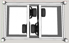
Exterior dimensions are 1200 long, 700 wide by 450 high. Ideally i'd like to keep this as small as possible, but need to still fit the four subs.
In the attached image, all walls are 25mm thick, the exterior walls being something like bamboo ply, and the interior ones being MDF.
My hope is that push-pull can help cancel out vibrations so coffee doesn't walk across my table.
My questions are:
How do I work out the aperture of the opening venting the subs to the room (the middle section)?
How do I work out how long the table legs should be, ie: how much space will be under the coffee table allowing the woofers to vent to the room?
What is the optimal way to wire these for push-pull?
Thanks!
Looking at building a coffee table push-pull subwoofer.
The drivers i'll be using are Oz Audio ME 12 woofers.
Specifications as follows:
Dual 4 ohm
FS (Hz) 34
QTS 0.66
QES 0.711
QMS 9.177
VAS 50.02
RE 3.3
XMAX 25
Sens (1W/1M) 86.46
Sens (2.83V/1M) 93.31
RMS/Peak (W) 500
Exterior dimensions are 1200 long, 700 wide by 450 high. Ideally i'd like to keep this as small as possible, but need to still fit the four subs.
In the attached image, all walls are 25mm thick, the exterior walls being something like bamboo ply, and the interior ones being MDF.
My hope is that push-pull can help cancel out vibrations so coffee doesn't walk across my table.
My questions are:
How do I work out the aperture of the opening venting the subs to the room (the middle section)?
How do I work out how long the table legs should be, ie: how much space will be under the coffee table allowing the woofers to vent to the room?
What is the optimal way to wire these for push-pull?
Thanks!
Attachments
If the two end enclosures are sealed and the middle section opens to the floor, and your dual voice coil drivers are individually wired in series for 8 Ohm each, I think this scheme will give you an 8 Ohm nominal load at the terminal and have everything in synch:
I think that will work very well for a single powerful amp, but not as well as building 4 separate sealed boxes (each of half the volume of one of your end enclosures) and spacing them around the room with smaller amps.
I won't address your other questions other than to say that my own down-firing coffee tables only have about 40mm legs and work extremely well. In my case the "escape path" between the four feet is just over half the piston area (SD) of the drivers for a kind of “slot loading” in which additional damping and mass are effectively added to the driver to extend LF response and possibly smooth overall response variations.
Big caveat though: I use a lot of electronic signal manipulation/boost, 18 inch C-V 1970s Sensuuround style cinema drivers and EQ for the room. I'm no expert on this stuff. I only know what works for me. My build is here: Hi-Fi Projects Coffee Table Subwoofers
An externally hosted image should be here but it was not working when we last tested it.
I think that will work very well for a single powerful amp, but not as well as building 4 separate sealed boxes (each of half the volume of one of your end enclosures) and spacing them around the room with smaller amps.
I won't address your other questions other than to say that my own down-firing coffee tables only have about 40mm legs and work extremely well. In my case the "escape path" between the four feet is just over half the piston area (SD) of the drivers for a kind of “slot loading” in which additional damping and mass are effectively added to the driver to extend LF response and possibly smooth overall response variations.
Big caveat though: I use a lot of electronic signal manipulation/boost, 18 inch C-V 1970s Sensuuround style cinema drivers and EQ for the room. I'm no expert on this stuff. I only know what works for me. My build is here: Hi-Fi Projects Coffee Table Subwoofers
Thanks guys.
I currently have a JBL WGTI 15" sub underneath each main L/R speaker.
With this coffee table, that will bet three subs.
It's also the easiest way to get approval from SWMBO by only adding one piece of "furniture".
A fair while back I did a simulation with an acoustic company who uses proprietary software which put the best position for a single subwoofer at just past the half way point in the middle my room. It also put the ideal listening position at the same point. I can't move the listening position but I can put the coffee table in the mirrored position in front of the listening position. Sadly i no longer have this data available though.
Hoping this (with all 3 subs) helps give good even bass across multiple listening positions.
... Now to finish off bracing and determine the cut plan.
It should be placed where it measures best, but if mid wall is all you can do, that will help the ameliorate the first horizontal mode.A fair while back I did a simulation with an acoustic company who uses proprietary software which put the best position for a single subwoofer at just past the half way point in the middle my room. It also put the ideal listening position at the same point. I can't move the listening position but I can put the coffee table in the mirrored position in front of the listening position. Sadly i no longer have this data available though.
Hoping this (with all 3 subs) helps give good even bass across multiple listening positions.
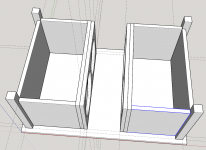
It will work either way with no performance difference. It will look neater as a piece of furniture with the sides installed as per first pic.
It will work either way with no performance difference.
Not so sure on that.
Hornresp can simulate the effects, but firing 4x drivers through a narrow slot will head towards a 4th order bandpass. The picture with the open sides will behave much closer to just sealed boxes.
Chris
Don't suppose someone would be so kind and simulate it?
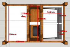
I've attached dimensions here.
There's a 75mm gap between the bottom of the table and the floor.
Hopefully this is enough information?
Also, planning to use bamboo ply so the stripes down the middle will be a "feature" 🙂
Much appreciated.
I've attached dimensions here.
There's a 75mm gap between the bottom of the table and the floor.
Hopefully this is enough information?
Also, planning to use bamboo ply so the stripes down the middle will be a "feature" 🙂
Much appreciated.
Attachments
I've actually built PP manifolds and they measure just like the equivalent sealed/ported enclosure without manifold until the manifold depth becomes significant. Not an issue for a sub but may be for a midbass.Not so sure on that.
Hornresp can simulate the effects, but firing 4x drivers through a narrow slot will head towards a 4th order bandpass. The picture with the open sides will behave much closer to just sealed boxes.
Chris
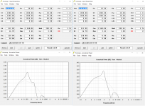
Here's some sims.
On the left, firing out of the bottom of the table, on the right, firing out the sides. Dimensions are approximate, and I've used different drivers. In both, the grey trace is a sealed box.
Note that with the left-hand simulation, the distance from the edge of the table to the drivers varies over a wide range. I guessed at an average. The variable distance will likely mean the peak is quite spread out when built.
Chris
Attachments
Thanks Chris,
Grey is sealed and black trace is that semi-bandpass arrangement?
Won't be using it over about ~80hz so will need a sharp filter if that's the case.
Grey is sealed and black trace is that semi-bandpass arrangement?
Won't be using it over about ~80hz so will need a sharp filter if that's the case.
Last edited:
That's correct, yes.
As I said, though, the one on the left (firing out around the bottom of the table) will have a variable distance from the edge of the table to the drivers, so the peak will be flatter and more spread out. YMMV.
Either way, I'd recommend measurement and EQ.
Chris
As I said, though, the one on the left (firing out around the bottom of the table) will have a variable distance from the edge of the table to the drivers, so the peak will be flatter and more spread out. YMMV.
Either way, I'd recommend measurement and EQ.
Chris
Many years ago, I found that my original sub, as described in the 1970s Linkwitz article simply didn't have enough output for our new, larger living room, I decided to build something larger that had high WAF. It would include 4 12" drivers and be housed in a 3000 cu inch box. One driver per side, with cross-bracing for all three dimensions. I placed a round "table-top" on top, and draped fabric on top.
The result was visually good, just another end-table. Sound was excellent, reaching down below 30Hz with plenty of available headroom. I still have it in the living room, though it's not connected at present, the 4 10" separate subs that I added to the original home design work just fine, too.
Opposing the 4 12" drivers yielded a box that simply does not move. Happy with that result, as we kept some fragile stuff on top. No, I reall don't have measurements on it anymore, that was 30 years ago.
"I've actually built PP manifolds and they measure just like the equivalent sealed/ported enclosure without manifold until the manifold depth becomes significant. Not an issue for a sub but may be for a midbass. "
+1
+1
Thanks guys.
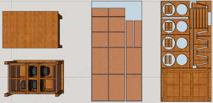
Final design completed, i can just squeeze this onto 2 sheets hopefully.
One sheet of 30mm, one sheet of 19mm.
Using Bamboo ply so the edge grain will be a "feature".
Since the 30mm sheet will need to be CNC'd i figure why not have an inlay CNC'd so that all pieces "slot" into the underside of the table top.
Attachments
- Status
- Not open for further replies.
- Home
- Loudspeakers
- Subwoofers
- Coffee Table Push-Pull Subwoofer