hope you ordered spare bits, .6mm is good for ordinary resistors (your hole will be more like .7), .8 or 1mm for the bigger stuff and a 1.2 is handy for larger pins like screw terminals, and the largest 2 you commonly use is 1.5 for large pins and 2.5 for M3 holes to be tapped in for screws and board standoffs. investing in a quality 2.5mm drill and engineering quality M3 tap is a godsend for this hobby.
Last edited:
Thanks to everyone's help, I've had a pretty successful first PCB design and construction adventure. I ended up with a two sided board to deal with the extra - rail and to deal with better routing around the potentometer. Note, as my original is drawn, the pot will turn on a full volume. Using the double sided board fixes that. In the image below, purple is board bottom, red is board top.
Works well with both OPA2134 and OPA 2228 using a gain of 6. I since moved to gain of 11. Additional info, IC pin blocking caps are 10uF 16V Nichicon electolytics. The only noise is a slight hiss with the source plugged in, none w/o source.
while both opamps work fine with a single 9v battery supply, only the 2134 will work with a dc wall wart. I've tried two different ones, one 18.7vdc the other 16.8vdc, both 500ma rating. The 2134 works fine with both, the 2228 will not work with either. I've tried lookign through the spec sheet but can't figure out what is wrong. The schematic I used is linked below, basically copied from diy4fun.blogspot.com. Exceptions are: only one TLE2426CLp was used. The blocking cap for the wallwart/LM317LZ is 22uF/25V electrolytic, as that is what I had. The adj resistor is 47R, giving I believe ~25mA of constant current.
Is my problem related to the constant current source, or value, or should I focus on the stabilizing feedback loop on the IC?
Thanks!

hammon1.3 by Dennis Dietz, on Flickr

diy4funpower by Dennis Dietz, on Flickr
Works well with both OPA2134 and OPA 2228 using a gain of 6. I since moved to gain of 11. Additional info, IC pin blocking caps are 10uF 16V Nichicon electolytics. The only noise is a slight hiss with the source plugged in, none w/o source.
while both opamps work fine with a single 9v battery supply, only the 2134 will work with a dc wall wart. I've tried two different ones, one 18.7vdc the other 16.8vdc, both 500ma rating. The 2134 works fine with both, the 2228 will not work with either. I've tried lookign through the spec sheet but can't figure out what is wrong. The schematic I used is linked below, basically copied from diy4fun.blogspot.com. Exceptions are: only one TLE2426CLp was used. The blocking cap for the wallwart/LM317LZ is 22uF/25V electrolytic, as that is what I had. The adj resistor is 47R, giving I believe ~25mA of constant current.
Is my problem related to the constant current source, or value, or should I focus on the stabilizing feedback loop on the IC?
Thanks!
hammon1.3 by Dennis Dietz, on Flickr
diy4funpower by Dennis Dietz, on Flickr
More info, After looking over the board layout and considering how the power travels, I tried to bypass the LM317LZ part. As soon as I bypass it, the amp works. In fact, if I bypass it with the amp on (the switch and LED is on, no sound) sound begins and I can remove the jumper and the amp continues to work un-bypassed. This leads me to believe there is an issue with the LM317 itself or the circuit needs a differnet value/component. As mentioned, I am using a 22uf el cap instead of the 10uf tantalum specified my diy4fun.
Quesient current draw with a power supply is ~20mA. With battery it is ~10mA. My tester is only capable of measuring in 0.00A. Readings are consistent regardless of how many times I measure them and for the power supply, whether or not the LM317 is bypassed.
Do I need a different capacitor, different resistor voltage, different transistor???
Just checked the voltages and find that with the lm317 not bypassed, the voltage after the charge circuit is 3.8vdc from a 18vdc wall wart. If I bypass the transister so that the amp works, the voltage after the charger circuit is 11.9vdc.
Thoughts? I'll try changing the charger capacitor as Ive read that when substituting el caps for tantalum you need about 10x more and I currently only have 2x more. I don't know if that matters or not, but I'll try it.
Thoughts? I'll try changing the charger capacitor as Ive read that when substituting el caps for tantalum you need about 10x more and I currently only have 2x more. I don't know if that matters or not, but I'll try it.
Switching to a 100uf/25V el did nothing.
But, I guess I need to learn to read. I had checked the National website a few times to double check the pin arrangement of the LM317. Guess i transposed it in my head or something but I had it in backwards. (embarrassed face icon).
Anyway, it works great now.
But, I guess I need to learn to read. I had checked the National website a few times to double check the pin arrangement of the LM317. Guess i transposed it in my head or something but I had it in backwards. (embarrassed face icon).
Anyway, it works great now.
It certainly does. Thank you Digits for all your help.
I actually wish (sort of) that the 2228 had been problematic as i would like to know how to troubleshoot and fix the problem. Maybe next time.
My next project, after I build a second of these for a friend, are active, near field vocalist stage monitors. Or maybe a 3886 gainclone.....
I actually wish (sort of) that the 2228 had been problematic as i would like to know how to troubleshoot and fix the problem. Maybe next time.
My next project, after I build a second of these for a friend, are active, near field vocalist stage monitors. Or maybe a 3886 gainclone.....
Maybe I can have the opportunity to learn and tweak a little. I get a little hiss when source is plugged in. Source volume does not affect hiss. Hiss level does vary with different sources. My computer is pretty hissy (only noticeable when there is not sound) but my iphone is nearly silent.
Is there anything I can do for noisier sources that will not affect sound or gain to much? I'm using a OPA2228.
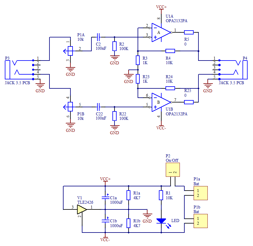
A second question, can I use a higher gain than 11? The drawing below pulled from a google search (source at electronics-diy.com) shows the resistor values I am using. Ignore the power supply part. Can I change R3 or R4 to get higher gain? Maybe R4 to 15Kohm for a gain of 16? Or make R3 smaller (maybe 470ohm)? would there be an advantage to one change over the other?
Thanks again!
Is there anything I can do for noisier sources that will not affect sound or gain to much? I'm using a OPA2228.
A second question, can I use a higher gain than 11? The drawing below pulled from a google search (source at electronics-diy.com) shows the resistor values I am using. Ignore the power supply part. Can I change R3 or R4 to get higher gain? Maybe R4 to 15Kohm for a gain of 16? Or make R3 smaller (maybe 470ohm)? would there be an advantage to one change over the other?
Thanks again!
Last edited:
Thanks. I undetstood about R5 but thought it was more for noise in the amp rather than source noise. May I ask how you arrived at the value of 56ohm and is there a formula for determining that value and how it will affect output.
Would it be better at R5 or further away on series with the output?
Would it be better at R5 or further away on series with the output?
well, its a stopgap, not a perfect solution, but it works for some, it also depends on the phones you are useing... what are you useing as a source?
P.S. put it close to the chip, not that I think it makes much diffirence...
P.S. put it close to the chip, not that I think it makes much diffirence...
Phones are 66ohm ATH-M30. Noisey source is my PC line/headphone out on the mobo. Clean source is an iphone.
I'll play with these things some, as well as experiment with the gain resistors for my own edification. Thanks!
I'll play with these things some, as well as experiment with the gain resistors for my own edification. Thanks!
Ahh, K you are probably picking up noise from the switchmode supply....
I'd try and get a PCM2706 dac design, and use optical or toslink output from PC....
I'd try and get a PCM2706 dac design, and use optical or toslink output from PC....
Ahh, K you are probably picking up noise from the switchmode supply....
I'd try and get a PCM2706 dac design, and use optical or toslink output from PC....
Well, there is quite a jumble of wires around my desk so I'm sure I am picking up some stray noise through the line. Did you mean switchmode supply on my computer or on the wallwart, because the hiss is there when the amp is using only battery power. No hiss if no line in connected but amp located in same place.
I'll have to Google everything in your second sentence as its all greek to me🙂
Found a new issue though, I have populated the second board and find the TLE2426CLP is not passing things right and is getting very hot on only battery power. I did have the 12V/1.0w zener in backwards the first time I applied power, could that have damaged the rail splitter? I am now positive that everything is connected correctly. I can change the rail splitter as I have extra, but it will have to wait till later in the day.
Thanks again for all the help!
PC supply would be my guess, yes you could have damaged the splitter... expensive little buggers...
PCM2706 USB DAC with I2S as an example... it gets its input via USB from the PC....
PCM2706 USB DAC with I2S as an example... it gets its input via USB from the PC....
Yup, must have damaged the first splitter. Replaced it and all was fine. Expensive... sort of, cost about $1us so not to bad.I have a tendency to buy a couple extra of everything anyway so no biggie.
Interesting with the DAC. I have other priorities first though....
Thanks!
Interesting with the DAC. I have other priorities first though....
Thanks!
I'd like to point out two important things...
First, in the last PCB layout I posted, the LM317LZ at the top is shown reversed. Pin one should be at the bottom. Also note, it is important to double check the data sheet to determine orientation. I layed out the PCB using in error (Mouser linked to the wrong sheet) the LM317L. That datasheet, the one linked in my post 1, shows a pin out reversed from the LM317LZ. I can't seem to edit my older posts to note this.
Second, I have tried the OPA2228 with a gain of ~22 using resistor values of 10K for R3 and 470R for R4, with gain calculated as R4/R3+1. This might be a bit high for gain but it works very well for my current situation. I've not tried this gain with a different opamp yet.
Last, I'd just like to say I've been listening to Paul Simon today and wow, I had never realized how much detail was in his music. I really like the 2228 compared to the 2132/4. very nice.
A gain of 11 is very high for a headphone amplifier. That could be part of your excessive noise problem.
An even higher gain of 22 should never be required.
100mW (very loud) into 66ohm headphones is ~2.5Vac.
A gain of 11 would require an input from a source to be ~250mVac at maximum output level, or more like 20mVac at sensible levels.
Divide these voltages levels by ~2 to get the required signals for a 22X gain amp, i.e. 120mVac absolute max and 10mVac for sensible listening.
Thanks Andrew. I was really interested in simply seeing if that gain was possible for my own edification. I find that with an ipod nano or an iphone, source volume at 25% and amp volume at ~75% (pot rotation) is my ideal max listening level using the ATHM30 phones. These phones require me to turn up the source, when used alone, to almost full blast. I do tend to listen a little loud, I admit, but not excessively loud. Also, after spending the early part of my life in a place where hearing protection was never considered while the machinery, trucks, and music where damagingly loud, I need a little more volume these days.🙁
Anyway, yup, the high gain does increase the inherent noise level of the input to much. Its nice having two identical amps to play with though as I'm really interested in comparing changes.
Anyway, yup, the high gain does increase the inherent noise level of the input to much. Its nice having two identical amps to play with though as I'm really interested in comparing changes.
results from experimentation are usually remembered for a very long time.
Try a gain of 4times (+12dB), instead of 11times (+20.8dB). It may just be loud enough with your lowest source voltage and reduce the noise very slightly.
Basically you should be setting all your digital sources to output maximum signal and then use an attenuator or amplifier to bring the signal to a listen-able level. Then use the attenuator/amplifier to adjust SPL to suit different listening moods.
Last edited:
- Status
- Not open for further replies.
- Home
- Amplifiers
- Chip Amps
- CMOY pcb -my first pcb