Post1 shows output capacitors.
Post4 refers to those schematics.
There are no other schematics, prior to post4.
Actually post 1 includes both the cmoy schematic without output caps, see right bottom thumbnail, and the headbanger with output caps.
Thanks 00940. At least I'm not the only one confused.
Andrew, I've read lots of your posts and you always give very knowledgable advice. I realize I'm a noob here and you've helped a lot of people, but I'm having a hard time feeling it from you here. I do sincerely thank you for your help, but I can't help feel your ot actually reading anything I post. I don't expect anything from you, or from anyone here, but you and I seem unable to communicate. I really don want to ge off on the wrong foot, but honestly your answers in this thread don't seem to be well thought out.
To all, I will have time tomorrow to sit down with the circuit and be vey systematic in responding to all that I've read here. Thanks to everyone, honestly, for everything so far. I've really learned a lot already!
After a few dozens charge cycles, I'd be surprised if two batteries still held the same charge and had the same behavior. I've also had rechargeable dying on me (with pretty much a switch behavior). Furthermore, there's always the possibility to put a charged battery and an uncharged/partially charged one in the amp. Yes, it's careless... but anyone's mind can wander at times and a full battery and an empty one don't look that different.All the more likely they'll have near identical charge then.
If an offset drawing current does develop, it will be small but it will tend to equalise the batteries as the drain will be differential. Battery discharge is not like a switch being thrown. The likelihood of drawing sufficient current to damage phones is vanishingly small.
Actually, I didn't. I thought I made clear in my post just above that a resistor+caps rail splitter will have lower performance than using the center of two batteries. However, that level of performance is still more than enough for a simple cmoy. A matter of trade-off. I'd rather have additional safety over a (near) unaudible performance gain. My opinion would be different for a more complex amplifier with better performance, for which the center tap batteries+offset protection would be justified.You have ignored the performance considerations. Even with an active virtual earth the performance will be poorer than the circuit I have suggested. This is because the input currents disturb the non inverting input more than is the case with the circuit I have described, because the impedance in the 'ground' path is inevitably higher than it otherwise would be.
No disagreement on this. It's trivial.The circuit about which I originally spoke uses a resistive divider. This is a compromise in terms of the resistance chosen. Lower resistance = better performing virtual ground, more wasted current. Higher resistance = less wasted current, poorer performing virtual ground.
No resistive divider or virtual ground = no wasted power.
Last edited:
OK, you prefer to sacrifice performance for your perception of safety. I prefer performance and efficiency over paranoia.
Oh, evidently Grado agree with me.
BTW, can you produce a link to any example of headphones destroyed by a failing battery?
w
Oh, evidently Grado agree with me.
BTW, can you produce a link to any example of headphones destroyed by a failing battery?
w
Last edited:
very confused.Actually post 1 includes both the cmoy schematic without output caps, see right bottom thumbnail, and the headbanger with output caps. 😕
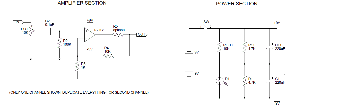
Both schematics show capacitors, 470uF, on the outputs.
It must be too small, I could not see it, not even when I went back to post1 to consult the schematics before commenting.
Then my sincere apologies Andrew. I've always seen that second image of the CMOY in post 1, and in fact I reproduced in on page two or three so I and others would not have to refer back to another page. Guess you missed that also😉
So, to be clear, when you said CMOY back in post 4, you where referring to the only image you saw, the LM3866 based Headbanger chipamp? I did understand what you meant about addin resistors to that one, but not to the CMOY, as should be for apparent reasons by now🙂.
So, to be clear, when you said CMOY back in post 4, you where referring to the only image you saw, the LM3866 based Headbanger chipamp? I did understand what you meant about addin resistors to that one, but not to the CMOY, as should be for apparent reasons by now🙂.
I can confirm that I have been referring to the two big schematics all along.
Sorry it took so long to iron out this confusion.
I didn't think I was going blind as well.
Sorry it took so long to iron out this confusion.
I didn't think I was going blind as well.
Last edited:
I've finally had a chance to sot down with this so I'll start by going through Mooly's steps from back on page two (post 20) quoted below.
I've started with the amp built base don the schematic you posted with some exceptions. These are:
1.0uf polyester caps at input.
No parallel output cap.
No cap across pins 4 and 8.
No additional series output resistor.
With a 9V supply and no source, I have DC offset of 0.1mV on negative rail side, 1.6mv on positive rail side. With source connected and playing, DC offset stays the same. Source is an ipod. DC from source alone is 3mV max at full volume. DC offset at amp output with source at full is 0.1mV on negative rail and 1.6mv on positive rail.
Sound is good, there is not distortion I can hear with either cheap ear buds or better ATHM30 headphones (66ohm impedance). Sound quality seems, to my ear, about the same in terms of amounts of base, mid, and high frequencies compared to the same phones directly into the source. In other words, the increased input cap size seems to have fixed the bass loss issue I had with smaller 0.1 and 0.22uf polyester caps.
Adding a 0.1uf ceramic cap across pins 4 and 8 (V+ and V- of chip) makes no audible difference.
Adding a 69pf ceramic across R4 makes not audible difference.
I've not tried anything serious yet with a series output resistor.
To my ear there is no distortion with these changes.
The sound overall is ok, not really an improvement over the source but sine the source can be much lower, there is less source issues since I am currently only using this with MP3. I'm anxious to try this with better source, like a CD.
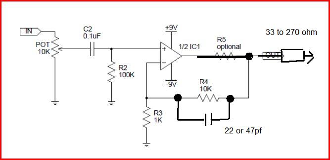
1. I couldn't just see any reference of yours to R5 so lets short it out for now.
2. Make sure you have a small cap of at least 0.1uf across pins 4 and 8. Just one cap. The value isn't critical, even a 10 or 100uf electroylitic is fine.
3. With no phones and nothing connected to the input measure on DC volts from "ground" to the output pins 1 and 7 and report back the readings. It should be essentially 0.000 volts... a millivolt or two at most. If it's not zero does step 5 kill the offset.
4. If that's OK now try the amp. Is it distorted ?
Without an oscilloscope it's impossible to know exactly what is occuring but this is such a basic text book application we can make a good guess.
5. To eliminate the possibility of oscillation I would add a 22 or 47pf (pico) cap across R4. Test again for distortion.
6. Depending on the phones an output resistor may be advised and this is trial and error but try something like 33 to 270 (or higher) ohms
in series with the output to the phones. Start high and work down. With an 18 volts (-/+ 9v) supply the opamp really should not be working into less than 600 ohms load for full output. Phones don't need that of course but if the impedance is very low the opamp may not deliver much voltage swing at all. So try the resistor. Keep R5 shorted for now and add the resistor after that point as shown.
Input caps... with 100k for R2 you really need around 1uf (a small electroylitic is OK).
I've started with the amp built base don the schematic you posted with some exceptions. These are:
1.0uf polyester caps at input.
No parallel output cap.
No cap across pins 4 and 8.
No additional series output resistor.
With a 9V supply and no source, I have DC offset of 0.1mV on negative rail side, 1.6mv on positive rail side. With source connected and playing, DC offset stays the same. Source is an ipod. DC from source alone is 3mV max at full volume. DC offset at amp output with source at full is 0.1mV on negative rail and 1.6mv on positive rail.
Sound is good, there is not distortion I can hear with either cheap ear buds or better ATHM30 headphones (66ohm impedance). Sound quality seems, to my ear, about the same in terms of amounts of base, mid, and high frequencies compared to the same phones directly into the source. In other words, the increased input cap size seems to have fixed the bass loss issue I had with smaller 0.1 and 0.22uf polyester caps.
Adding a 0.1uf ceramic cap across pins 4 and 8 (V+ and V- of chip) makes no audible difference.
Adding a 69pf ceramic across R4 makes not audible difference.
I've not tried anything serious yet with a series output resistor.
To my ear there is no distortion with these changes.
The sound overall is ok, not really an improvement over the source but sine the source can be much lower, there is less source issues since I am currently only using this with MP3. I'm anxious to try this with better source, like a CD.
So, I've played with this some more and i still am finding very poor bass response compared to straight from the source. My first amp has good bass response, almost identical to the source.
At this point, there are three things different: The input caps (0.1uf polypro = good bass, 1.0uf polyester=bad bass), and the opamp used (good = OPA2132PA, bad=OPA2134PA). The logical step is to change the opamp, but the original is buried inside its enclosure, "hidden" by hot-glue and solder🙁 I can't get polypro caps locally🙁 Last, the original runs on a 9VDC/150mA wall wort, the new amp has a new 9v alkaline battery.
Adding a 10K resistor in series before the input cap returns the bass, but that kills most of the volume. Interestingly, a 10K ALPS pot at max resistance does not have the same effect- though I did not solder it but used alligator clips????
Is bass response really this strongly affected by the cap type used at the input?
I'll have to look at this more tomorrow.
Thanks in advance!
Only the value of the cap will affect bass response, not it's type. The lower the value of the cap the "worse" the bass response, so I can't reconcile your statement of 0.1=good and 1.0 = bad. In the posting above that #50 you say
"about the same in terms of amounts of base, mid, and high frequencies compared to the same phones directly into the source. In other words, the increased input cap size seems to have fixed the bass loss issue I had with smaller 0.1 and 0.22uf polyester caps. "
A cap and resistor (C2 and R2) in the above diagram form a simple "first order" high pass filter.
High-pass filter - Wikipedia, the free encyclopedia
Are you 100% sure you are interpreting the markings correctly ?
The opamp has no influence on bass response.
"Adding a 10K resistor in series before the input cap returns the bass, but that kills most of the volume. Interestingly, a 10K ALPS pot at max resistance does not have the same effect- though I did not solder it but used alligator clips????
If the 10k is inserted before C2 in the above diagram and it kills the volume then that points to R2 not being 100K. If so it would also explain extreme lack of bass with a 0.1uf cap so measure and check all the values (out of circuit).
This will help you understand the cap and frequency cut off values, just type your values in to the calculator to see how it works out with different R and C values.
RC pad corner frequency cutoff calculation calculate filter time constant tau RC voltage power calculator capacitance resistance - sengpielaudio Sengpiel Berlin
RC pad corner frequency cutoff calculation calculate filter time constant tau RC voltage power calculator capacitance resistance - sengpielaudio Sengpiel Berlin
Thanks for the reply Mooly!
I actually posted a bi last night that seems to have not shown up. I don't know if it is lost in cyberspace or, most likely, I hit the wrong button, closed the browser and quit for the night.
Anyway, I meant to say last night that my earlier comments in post #50 about the bigger caps being
was worng! There was an improvement but after comparing the old to new and new to source more closely, I am still missing a lot of the bass.
Mooly said:
Hit the nail right on the head. The noob that I am, I pulled two resistors out of a bag marked 100K and stuck them in for R2 (after covering them with heat shrink to prevent the vertical orientation from shorting on other parts) without check their markings or with a meter. Thanks to your suggestion, I removed the heat shrink and what to I find, 1K.
Embarrassing but at least I know more know. I'm off to my shop to switch out the resistors and go from there.
Question in the mean time, what does a serial resistor at the output do? Does it increase the output resistance, there by making the whole circuit draw more current???
I actually posted a bi last night that seems to have not shown up. I don't know if it is lost in cyberspace or, most likely, I hit the wrong button, closed the browser and quit for the night.
Anyway, I meant to say last night that my earlier comments in post #50 about the bigger caps being
"about the same in terms of amounts of base, mid, and high frequencies compared to the same phones directly into the source. In other words, the increased input cap size seems to have fixed the bass loss issue I had with smaller 0.1 and 0.22uf polyester caps."
was worng! There was an improvement but after comparing the old to new and new to source more closely, I am still missing a lot of the bass.
Mooly said:
Are you 100% sure you are interpreting the markings correctly ?
and
If the 10k is inserted before C2 in the above diagram and it kills the volume then that points to R2 not being 100K. If so it would also explain extreme lack of bass with a 0.1uf cap so measure and check all the values (out of circuit).
Hit the nail right on the head. The noob that I am, I pulled two resistors out of a bag marked 100K and stuck them in for R2 (after covering them with heat shrink to prevent the vertical orientation from shorting on other parts) without check their markings or with a meter. Thanks to your suggestion, I removed the heat shrink and what to I find, 1K.
Embarrassing but at least I know more know. I'm off to my shop to switch out the resistors and go from there.
Question in the mean time, what does a serial resistor at the output do? Does it increase the output resistance, there by making the whole circuit draw more current???
No wonder you had no bass. With R2=1k you were already 3dB down at 160Hz.
You got it backwards - as resistance increases, current decreases, voltage being equal. Ohm's law. What the resistor does is indeed decrease useful power to the load, HOWEVER, it also does one additional thing - The opamp is spec'd to deliver its specified current on a specified load resistance (hence a specified voltage). If the load resistance is lower, the voltage output for the same current decreases. This may cause distortion.
What the resistor does is that opamp always "sees" a minimum load resistance of the value of the resistor, regardless of the impedance of the phones. Thus a certain level of voltage swing at the output of the opamp is guaranteed, preventing distortion under high loads - low impedance phones will simply decrease the loudness.
Question in the mean time, what does a serial resistor at the output do? Does it increase the output resistance, there by making the whole circuit draw more current???
You got it backwards - as resistance increases, current decreases, voltage being equal. Ohm's law. What the resistor does is indeed decrease useful power to the load, HOWEVER, it also does one additional thing - The opamp is spec'd to deliver its specified current on a specified load resistance (hence a specified voltage). If the load resistance is lower, the voltage output for the same current decreases. This may cause distortion.
What the resistor does is that opamp always "sees" a minimum load resistance of the value of the resistor, regardless of the impedance of the phones. Thus a certain level of voltage swing at the output of the opamp is guaranteed, preventing distortion under high loads - low impedance phones will simply decrease the loudness.
Pleased you found what the problem was, easy error to make.
Pretty much answered above... the opamp output can be considered an ideal voltage source at the output but with a strict limit on the current that can be drawn. So any load that causes that current level to be reached causes the opamp to limit the output voltage. In other words it becomes more like a constant current source.
An opamp that can deliver -/+15 volts into 600 ohms needs to be able to supply at least -/+25ma. Lets assume that current is the maximum specified in the data sheet. Reduce the load to 100 ohms and as soon as -/+25ma is reached which is 2.5 volts (-/+2.5), then the opamps current limit is reached.
Also, if you were always driving 100 ohms as in this example then there would be no point running the opamp on a high supply voltage.
With the headphones it's very much trial and error to make the most of the voltage swing available while ensuring adequate max volume.
Also some opamps can be unstable when presented with a small capacitive load directly on the output (usually high speed opamps) and a few 10's of ohms in series with the load isolates the opamp from that and keeps it stable. That capacitance may be something as small as the cable its running into.
Question in the mean time, what does a serial resistor at the output do? Does it increase the output resistance, there by making the whole circuit draw more current???
Pretty much answered above... the opamp output can be considered an ideal voltage source at the output but with a strict limit on the current that can be drawn. So any load that causes that current level to be reached causes the opamp to limit the output voltage. In other words it becomes more like a constant current source.
An opamp that can deliver -/+15 volts into 600 ohms needs to be able to supply at least -/+25ma. Lets assume that current is the maximum specified in the data sheet. Reduce the load to 100 ohms and as soon as -/+25ma is reached which is 2.5 volts (-/+2.5), then the opamps current limit is reached.
Also, if you were always driving 100 ohms as in this example then there would be no point running the opamp on a high supply voltage.
With the headphones it's very much trial and error to make the most of the voltage swing available while ensuring adequate max volume.
Also some opamps can be unstable when presented with a small capacitive load directly on the output (usually high speed opamps) and a few 10's of ohms in series with the load isolates the opamp from that and keeps it stable. That capacitance may be something as small as the cable its running into.
I already answered to that output resistor question earlier on but let's do it again.
The only reason to use output resistors is the isolation from capacitive loads. 10r is usually more than what's needed with an opa134 and it's actually not needed at all most of the time.
As for "making the most of the voltage swing", that doesn't make sense. The output resistor acts as a voltage divider. The voltage accross the headphones drivers (and thus the power delivered) will actually be at its maximum for all headphones impedances without an output resistor.
The peak voltage will be X ohms * 40mA, X being your headphones impedance and 40ma the short circuit current of an opa134. That peak voltage cannot exceed the power rails minus 3v or so. Any resistor added at the output will reduce the available voltage swing. It doesn't matter at low impedance as we're current limited way before being voltage limited. If you'd use a 270r output resistor with a 300r pair of cans, you'd however lose half your power.
On top of that, output resistors can affect the frequency response of low impedance headphones and are best reduced to a minimum.
Typing too fast... half the voltage swing, 3/4 of the power (6db).If you'd use a 270r output resistor with a 300r pair of cans, you'd however lose half your power.
@Th3 uN1Qu3: it is true that distortion would be better as the load goes up. Distortion figures are also better for output voltages above 1V (for the opa134). But a simple cmoy is an exercise in compromises and the frequency responses problems are more directly audible than the higher distortion. That's why adding a buffer in the feedback loop would be the first improvement I'd do on a cmoy. Easy enough with a pair of buf634.
I'll just add that for anyone with sensitive phones (and ears) and depending on the opamp and preceding stages that adding a series resistor does substantially cut the perceived "hiss" that can be audible from a direct connection to the opamp output.
Typing too fast... half the voltage swing, 3/4 of the power (6db).
🙂 Still typing too fast 😉
You mean you have lost 3/4 of the power in the series resistor.
Half the voltage swing generates one quarter of the power (in the load in this case the phones) which is as you correctly say 6db as a ratio.
- Status
- Not open for further replies.
- Home
- Amplifiers
- Chip Amps
- cmoy improved?