Hey Guys
to date i have built two different amps, the Headbanger (HeadBanger Headphone Amp Construction Kit) and The CMoy. Headbanger was based on LM386 while the CMoy on OPA2132PA.The question is about input and output caps and DC offset.
Cmoy has input caps (i selected 1mF and 0.1mF) and i get some DC offset on my headphones all the time.(headphones plugged in and not plugged in)
But the Headbanger
has Caps on the output stage, and as soon as any load is put onto the amp (my headphones for example) the DC offset goes to 0.
i read articles at tangentsoft about weakness of caps when in signal lines (Bass Roll Off, Phase distortion, Cap Distortion)
Input Capacitors for Headphone Amps
now my question is, when caps are placed in the output stage, is there no Bass Roll-Off, Cap distortion and phase distortion? if there isnt, is there a way to implement caps at output stages rather than on the input lines in the cmoy? would that be beneficial?
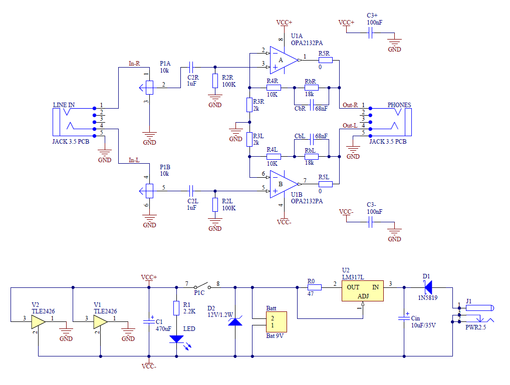
Both Schematics are attached
to date i have built two different amps, the Headbanger (HeadBanger Headphone Amp Construction Kit) and The CMoy. Headbanger was based on LM386 while the CMoy on OPA2132PA.The question is about input and output caps and DC offset.
Cmoy has input caps (i selected 1mF and 0.1mF) and i get some DC offset on my headphones all the time.(headphones plugged in and not plugged in)
But the Headbanger
has Caps on the output stage, and as soon as any load is put onto the amp (my headphones for example) the DC offset goes to 0.
i read articles at tangentsoft about weakness of caps when in signal lines (Bass Roll Off, Phase distortion, Cap Distortion)
Input Capacitors for Headphone Amps
now my question is, when caps are placed in the output stage, is there no Bass Roll-Off, Cap distortion and phase distortion? if there isnt, is there a way to implement caps at output stages rather than on the input lines in the cmoy? would that be beneficial?
Both Schematics are attached
Attachments

The circuit you posted runs on a single rail so the output is at half supply. With no phones plugged in you will read voltage on the H/phone socket as the cap has been unable to "charge". As soon as you plug phones in it will drop to zero.
As long as the caps are sized appropriately for the load there will be no audible roll off.
470uf is fine.
The CMOY should have an offset in the millivolt range using FET opamps. If using Bipolar then there will be significant offset as the opamp input bias currents (resistors) are not equal.
So if there is an offset you need to find out why.
What is the offset measuring ?
hey mooly
my amp is based on OPA2132PA, not using electrolytics as input caps, also my offset, without headphones loaded is 6mV at max doesnt cross this limit
i was actually impressed by the headbanger (lm386 based chipamp) and how the offset went down to a total 0 when the headphones were loaded. i'd like to ask though, is there any way to not have input caps but employ them in later stages as in the Headbanger?
HeadBanger Headphone Amp Construction Kit
Hi,
there are no charging/discharging resistors for the output caps.
You could add some high resistance from the output side of the caps to ground.
10k would do, but any value around there.
When Cmoy is OFF the 10k holds the tip and the ring at the same voltage as the ground. You can plug in headphones and no "click" to be heard.
When Cmoy is ON, the 10k takes any leakage current to ground leaving just AC signal on tip & ring. Again no "click" as you insert the phones.
When Cmoy is changed from ON to OFF or from OFF to ON the output capacitor has to change charge (voltage) from old state to new state. This requires current to flow. At the moment one side of the cap has all routes blocked with capacitors. No DC current can flow (until you plug in your phones). Change the circuit. It is a bad design. Add the two 10k resistors and sort what should never have been published.
The CMOY as you have posted will work OK with the input cap shorted... but it's not advisable because you rely on the feed into the amp being at 0.00 volts. Any slight offset would be amplified by the CMOY depending on the volume setting.
Andrews suggestion is good for adding a resistor to each output of the LM386 to ground (after the cap). Any amp that's AC coupled at the output will appear to have zero offset, so that in itself doesn't mean anything.
Andrews suggestion is good for adding a resistor to each output of the LM386 to ground (after the cap). Any amp that's AC coupled at the output will appear to have zero offset, so that in itself doesn't mean anything.
If you are interested in a high performance headphone amp without caps in the signal path, take a look at this one:- John Conover: Direct Coupled Stereo Headphone Amplifier
w
w
As a dense noob, I'm curious about AndrewT's post above. I'm going to add my little story to this thread since they seem very similar.
The CMoy has no output capacitor. Are you talking about adding an output capacitor and resistor to ground for each output one OPA2132PA CMoy, or was that referring to the LM386 based amp?
I was just building a cmoy based headphone amp for a friend, after making one for myself. My works great and has very nice sound (IMO). I'm using 0.1uf 200V polypro input caps in that and have good bass response.
The new amp has almost no bass and distortion at volume spikes of transients. The new amp differs from the old in a couple ways. I'm using a OPA2134PA instead of the 132PA on the first. I read that these might be a little finickier. Also, the input caps on the new are 0.15uF polyester (the little green rounded rectangle kind) pulled from the parts bin.
Aside from bass loss (capacitor related) I get some DC at the outputs. One side is 0.6mv max, the other is 1.6mV max.
Bypassing the input caps leads to a better sound. Its much louder and has less distortion, but there is still a little on the heavy bass. My sources so far have low enough DC that I felt safe trying it bypassing the input caps.
Input is MP3 from ipod. I'm using 66R headphones and cheap earbuds. Distortion (crackly at louder parts and higher volume- but not that high) is apparent in both.
Should I try changing the opamp chip, different input caps, or bypass the input caps and add output caps with a grounding resistor? Obviously I'd like to try all but...I can get different caps locally but have to order the chip so I'd like to try and get this chip working. Also, I have cleaned the flux and checked all my solder joints.
Thanks for reading!
I think you have current clipping.
What is the impedance of your headphones?
What is the average voltage you listen at?
What is the impedance of your headphones?
What is the average voltage you listen at?
Thanks for the reply.
Headphones are cheap apple earbuds (don't know impedance) and 66 ohm ATH 3O.
Clipping happens at all volume of source level. Not sure the listening voltage but lll try to check it.
Headphones are cheap apple earbuds (don't know impedance) and 66 ohm ATH 3O.
Clipping happens at all volume of source level. Not sure the listening voltage but lll try to check it.
0.15 caps all things being equal will give "more" bass than 0.1's when used as input caps.
The DC offset at the out is minimal and should be an issue.
Have you tried add a small cap of say 10uf directly across the opamp supply pins ?
The DC offset at the out is minimal and should be an issue.
Have you tried add a small cap of say 10uf directly across the opamp supply pins ?
I cannot measure VAC on the input with my multimeter, it does not go low enough.
VDC on input, from one side to ground, if as high as 55mV (55 on side, 45 other side) without headphones on and ~4 mV with headphones connected. That uses my computer soundcard as source. An iPod has input VDC ~1mV headphones on or off.
My next steps are, double check all resistor values, try small ceramic cap from V+ and V- on opamp to ground (from http://www.diyaudio.com/forums/chip-amps/111733-cmoy-amp-troubleshooting.html, starting at bottom of page 1), consider RC set at output and bypass input, try better caps for input or output.
It seems to me, since I did not have this issue on my first amp, is that I either need different input caps or better stabalization of the opamp since am using a different opamp but same sources and all other parts are the same.
If I where to add an RC to either output or input (adding R to input for crossover control) what would be good values to start with?
Thanks again!
Mooly,
Thanks for your response. I thought that also about the input caps (some recommend as high as 0.47uF).
Wait, DC offset is minimal and should, or should not be an issue??? I've read a 20mV max but don't remember where and I realize if you look hard enough you'll find any recommendadion on the net.
small ceramic cap across opamp supply was my next thought, based on reading.
Should it go between the pins only, or from each pin to ground (using 2 caps). I've seen 0.0-10uf recommended, does it matter?
Thanks!
Well,
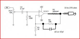
I've been doing some reading and also playing with this a bit more today. Attached below is a copy of the schematic I am using, basic from tangent. I'm not using R5. R3 is 2K, to give a gain of 6. The input caps are 0.1uf polyester from radioshack (the green candy-like ones).
I went over the circuit again and checked my values and connections. I replaced the original 0.1uf input caps, which were used from an old phone board. I also found that the 10K R4 was about 7.5K instead so replaced those.
This fixed a lot of the problem. The cap is still eating most of the bass but distortion is eliminated until the source (ipod) is at max volume. Adding a resistor in series before the input cap brings back the bass and increases the volume. I tried 10K, since a potentometer for volume later would be 10K and that helped a lot. Exchanging in a 1k resistor has less bass and lower volume.
If I bypass the input cap (and resistor if its there) I get max volume but it does not sound great. I believe the bad sound is due to DC offset (is that the right term, DC in the audio line). At max gain and input, DC at the output can hit ~30mV. Obviously I'm not using my goop phones for this! As expected, loudest sounds produce the highest DC at output and the worst distortion (crackle). Adding a resistor in series to the input lowers the volume and cleans up the sound some since it reduces the DC from source.
Now, what follows is something I don't understand. The amp, with a gain of 6, is quieter than the source if I use the input capacitor and I believe it is also lower than the source with the series resistor (10K).
Why, I've checked everything several times. If I bypass the cap/resistor, its obviously amplified, but sounds bad due to DC.
My other amp, identical except for the type of input cap (polypropolyene instead of polyester, both 0.1uf) and chip(OPA2132PA on original, 3124PA on new), has a good sound, reasonable bass and obvious amplification (both gain=6).
So, what should I do to improve this from here????
I don't want to use the polypro caps on this one since they are huge and my goal is as small as possible. I saw a blog post where someone added an RC loop in series with R4 and parallel with the chip output pin in order to improve the bass. See here:
diy4fun: CMoy for Altoids box
I've also included the person's schematics at the bottom of my post for reference.
I would try this but I can't find a suitable capacitor today. If adding an RC out is the way to go, do I keep input cap as in previous link or remove it? If RC output is the way to go, what would suitable values be? Sorry, newbie question.
Thanks in advance!!
Now for one last thing.
Can this be optimized to use a 2xAA batteries? As I may have mentioned, I'm making this for a friend and would like to to be as portable as possible - he already has plenty of non-portable audio gear.
I tried my current setup with 2xAA rechargeables. Very scratchy and distorted but if I bypass R1 (the 4.7K resistors making the virtual ground) the sound was good, just lower volume. If my math is correct, comparing the resistor value for 9vdc source and using Ohm's law, I get ~1.5K as values for R1 with 2xAA sources. I suspect it is more complicated than that and I know the datasheet set minimum voltage at +- 2.5vdc. I suspect rechargable 9vdc is the way to go, but greatly increases the startup cost.
Thoughts?
2x AA isn't enough unless you're making a tiny switchmode power supply to go with it. I had such a project planned last year but didn't build it because i got a proper media phone (SE w595) and it has plenty of power and bass.
Your lack of bass is also related to the OPA2132's low current output. You'd need a little output stage for that to work on low ohm phones like the common 32 ohm variety.
Your lack of bass is also related to the OPA2132's low current output. You'd need a little output stage for that to work on low ohm phones like the common 32 ohm variety.
2x AA isn't enough unless you're making a tiny switchmode power supply to go with it. I had such a project planned last year but didn't build it because i got a proper media phone (SE w595) and it has plenty of power and bass.
Your lack of bass is also related to the OPA2132's low current output. You'd need a little output stage for that to work on low ohm phones like the common 32 ohm variety.
I suspected that with smaller batteries. But as for bass, the other cmoy I have with different capacitors (polypro) has plenty of bass. That is with 66ohm headphones.
Post13
Are you feeding that CCS + shunt regulator with batteries?
If your referring to the schematic I posted, I explained in the text that it is someone else's design and I linked the source where it is described.
I referenced it to show the output RC loop that supposedly adds extra bass. I wondered peoples thoughts on that.
Basically, you - AndrewT- alluded to the fact that the cmoy is a poor design and mentioned a few things that might improve it. I feel like those improvements where mentioned in passing and my limited experience prevents me from fully understanding what you meant.
I'd really love to learn more. If my previous posts are too long, and tl&dr happened, let me know and I'll try to shorten my posts. I do feel that providing as much info as possible is more useful than having to clarify.
Thanks!
Well, if anyone is watching, here is what I did tonight.
I added a bass boost RC circuit in series with the feedback resistor (R4 on the tangent schematic in case I'm using the wrong terminology) and in parallel with the the chip out (pin 7 or 2). I used a 0.1uf polyester metal film in parallel with a 15k 1/4watt resistor. This gave a nice deep bass (maybe to much - but I think decreasing the resistance lowers the bass gain), especially with bypassing the input capacitor. The DC offset at the output jack in this configuration (bypassed input cap) is max 20mV. Still not ideal. Continuing to use the 0.1uf input cap kills all bass but reduces the DC offset to ~6mV max.
Andrew eluded to adding a resistor from the output side of the output cap to ground. I think that is what he meant. If that's true, Andrew or anyone have a recommendation for size?
I would still prefer to use an input cap as it makes better use of the board space. I might find a 1.0uf polyester metal film cap tomorrow and try those on input if they are not to huge size wise. That should roll the bass of very, very low (like 1.6x10^6 hz shoulder) and keep the cap distortion from affecting frequencies above audible -- assuming my reading is correct.
I also added a ceramic 0.1uf cap from the chips V+ and V- to ground. It made no audible difference but I was not expecting it to, as if I understand correctly, it prevents oscillation due to buffering "leftover" current to ground????
Thanks for listening!
A lot of post and qusetions so lets start with the basics,
I don't know how you are measuring resistor values but to get an accurate reading you must measure out of circuit by lifting at least one end.
Taking the circuit exactly as shown here lets try and build it up and check along the way.
1. I couldn't just see any reference of yours to R5 so lets short it out for now.
2. Make sure you have a small cap of at least 0.1uf across pins 4 and 8. Just one cap. The value isn't critical, even a 10 or 100uf electroylitic is fine.
3. With no phones and nothing connected to the input measure on DC volts from "ground" to the output pins 1 and 7 and report back the readings. It should be essentially 0.000 volts... a millivolt or two at most. If it's not zero does step 5 kill the offset.
4. If that's OK now try the amp. Is it distorted ?
Without an oscilloscope it's impossible to know exactly what is occuring but this is such a basic text book application we can make a good guess.
5. To eliminate the possibility of oscillation I would add a 22 or 47pf (pico) cap across R4. Test again for distortion.
6. Depending on the phones an output resistor may be advised and this is trial and error but try something like 33 to 270 (or higher) ohms
in series with the output to the phones. Start high and work down. With an 18 volts (-/+ 9v) supply the opamp really should not be working into less than 600 ohms load for full output. Phones don't need that of course but if the impedance is very low the opamp may not deliver much voltage swing at all. So try the resistor. Keep R5 shorted for now and add the resistor after that point as shown.
As to batteries and how much output swing is needed...
post #2 here gives details of actual measurements and the actual voltage swing needed across some Sony headphones in real use.
http://www.diyaudio.com/forums/headphones/160646-germanium-single-ended-class-headphone-amp.html
Driving low impedance loads from low supplies isn't as easy as it may seem... 2.5 volts is low when you start adding losses etc into the mix.
Input caps... with 100k for R2 you really need around 1uf (a small electroylitic is OK).
You shouldn't need any RC filters on input or output.
Attachments
- Status
- Not open for further replies.
- Home
- Amplifiers
- Chip Amps
- cmoy improved?