i dont know if this thread is supposed to be here, please move if this isnt the right place.
hey guys,
i have built 2 headphone amplifiers before, the HeadBanger, and another LM386 based one.the problems i have faced have always been with the grounds. i read the articles here on diyAudio by Sir Daven Davenport, but alas, even right now, its not very clear.
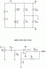
i am going to build a ChuMoy headphone amplifier, simple one, circuit attached. my question is, how do i deal with the grounds? do input grounds go separate and output grounds go separate? in the circuit, which ones are the output and input grounds, also, the ground from the power supply, what to do with that one?
i tried searching on the forums too, but didnt find anything much relevant, if there is something that i missed, please point out.and i did search google and everything, but its kinda like everything is going over my head.maybe with this circuit's example, i might understand.
thanks guys.
hey guys,
i have built 2 headphone amplifiers before, the HeadBanger, and another LM386 based one.the problems i have faced have always been with the grounds. i read the articles here on diyAudio by Sir Daven Davenport, but alas, even right now, its not very clear.
i am going to build a ChuMoy headphone amplifier, simple one, circuit attached. my question is, how do i deal with the grounds? do input grounds go separate and output grounds go separate? in the circuit, which ones are the output and input grounds, also, the ground from the power supply, what to do with that one?
i tried searching on the forums too, but didnt find anything much relevant, if there is something that i missed, please point out.and i did search google and everything, but its kinda like everything is going over my head.maybe with this circuit's example, i might understand.
thanks guys.
Attachments
All of your grounds should be connected together. Since you are using batteries, it's a floating ground supply, so it will reference whatever ground the device is connected to it uses and there should be no problem with ground loops. I would suggest connecting all grounds together in a star at one point.
If you are using a 3 conductor signal cable (two signals plus common ground, typical with 1/8" plugs), and splitting it to RCA input connectors, I would run a wire directly between the RCA grounds, and use that as the star ground, as there would be a small ground loop there and you want to keep it as small as possible.
If you are using a 3 conductor signal cable (two signals plus common ground, typical with 1/8" plugs), and splitting it to RCA input connectors, I would run a wire directly between the RCA grounds, and use that as the star ground, as there would be a small ground loop there and you want to keep it as small as possible.
Last edited:
Hi noobman92,
I also building this cmoy now, from what i learn from the internet your cmoy shematic is dual rail version, its ground using virtual ground for rail splitter. The grounding is simple, just do the star ground (no looping) and it will be ok. But the problem arise when splitting the single into dual rails using batteries, means to be portable. The Schematic you show, is using resistive splitter. Its not a good one, as the result will not equal between the rails. For the small load, less than 20mA, you can use TL2426 as the splitter, for bigger current handling use current feedback opamp schematic providing quite large current handling (250mA or more).
Virtual Ground Circuits
Hi,
I change a bit (changing the 1000uF or 470uF capacitor position to the front before the buffer and adding system bypass capacitor after the buffer) the sijosae virtual ground buffer schematic to be the circuit below. Is there something wrong with this configuration? About this buffer output impedance, how should i calculate it (quick calculation, no need to be accurate)? Any suggestion for the capacitor value?
Thanks before.
Roy
Uploaded with ImageShack.us
I change a bit (changing the 1000uF or 470uF capacitor position to the front before the buffer and adding system bypass capacitor after the buffer) the sijosae virtual ground buffer schematic to be the circuit below. Is there something wrong with this configuration? About this buffer output impedance, how should i calculate it (quick calculation, no need to be accurate)? Any suggestion for the capacitor value?
Thanks before.
Roy
An externally hosted image should be here but it was not working when we last tested it.
Uploaded with ImageShack.us
Last edited:
thanks redshift187 and sutantoroy for ur replies, i now better understand the grounding in this circuit.also, i the schematic uploaded by sutantoroy is not being maximised and i cant read it in that size.maybe upload again please.
thanks
thanks
Hi noobman,
Sorry for the picture, here is the better one:
Uploaded with ImageShack.us
Sorry for the picture, here is the better one:
An externally hosted image should be here but it was not working when we last tested it.
Uploaded with ImageShack.us
hey sutantoroy, i am a noob, and i have already built the power supply of the cmoy, measured it, and the voltage in the two parts is not totally identical, its like 5.00 and 5.01 volts.no problem here right? also, the grounding scheme u described, how do i implement it here in my circuit?
I am noob too...
For the grounding you can do just like redshift said, star grounding. The star ground means there is only one point one path for all grounds to meet. For instance just pull a path all your ground symbol to a point as center ground (IE: the point where the supply caps legs met).
Well, for the voltage you measured is okay. But is it measured with the load connected? As i try the first attempt to build as your schematic, it sounds very unbalanced sound level between left and right channels and with one channel distort heavily. I dont measure the voltage rail, but i think that is the effect of resistive rail splitter (my headphone is 150 ohms with power handling of 100 mW).
Last edited:
hey everyone
i read the article at tangent's, the virtual grounding one.i couldnt actually reach to a conclusion of using which transistor. i mean, my headphone impedance is 32ohms (power handling i dont know, but they are sennheiser hd212 pro), senstivity is 112dB. also, would my headphones use more then 20-40mA of current?the TL2426 would become unbalanced in that case.how do i calculate mex current my headphones would ask for? what do i do here? would just an TL2426 be fine?
i read the article at tangent's, the virtual grounding one.i couldnt actually reach to a conclusion of using which transistor. i mean, my headphone impedance is 32ohms (power handling i dont know, but they are sennheiser hd212 pro), senstivity is 112dB. also, would my headphones use more then 20-40mA of current?the TL2426 would become unbalanced in that case.how do i calculate mex current my headphones would ask for? what do i do here? would just an TL2426 be fine?
hey sutantoroy, i am a noob, and i have already built the power supply of the cmoy, measured it, and the voltage in the two parts is not totally identical, its like 5.00 and 5.01 volts.no problem here right? also, the grounding scheme u described, how do i implement it here in my circuit?
My cheap multimeter fluctuates that much depending on the probes' contact pressure.
Depending on how strict you are, +-5% is okay, 10mV out of 5V is 0.2%. But what you want to make sure is that the DC offset that the headphone sees is a few mV at most.
To increase current capacity of the virtual ground, connect the output of the TL2426 to the input of a buffer (high-current op-amp works too).
Then, after all this tinkering, it is not a CMOY anymore, but a mini3 😛.
It's all the same once you understand it...
- Status
- Not open for further replies.
- Home
- Amplifiers
- Chip Amps
- CMoy Grounds Trouble