I haven't had a chance to breadboard it yet, but simulations show greater distortion with the screen controlled servo amp than the cathode controlled servo amp.
I haven't had a chance to breadboard it yet, but simulations show greater distortion with the screen controlled servo amp than the cathode controlled servo amp.
Too much loop gain again. Try 10-50 ohms in series with D3.
jan didden
aeandm, the Zener diode actually works on the breadboard. It keeps VGs near 180V. Max screen voltage is specified as 170 for the 6P41S, and it I allow it to go much higher bias voltage must go much lower.
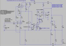
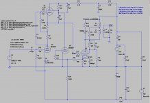
I do not understand your schematic. Am I supposed to bias the screen at a fixed level with the circuit shown?
janneman, I added 33 and eventually got it up to 51Ohms. that helps. tks.
I do not understand your schematic. Am I supposed to bias the screen at a fixed level with the circuit shown?
janneman, I added 33 and eventually got it up to 51Ohms. that helps. tks.
aeandm, the Zener diode actually works on the breadboard. It keeps VGs near 180V. Max screen voltage is specified as 170 for the 6P41S, and it I allow it to go much higher bias voltage must go much lower.
I do not understand your schematic. Am I supposed to bias the screen at a fixed level with the circuit shown?
janneman, I added 33 and eventually got it up to 51Ohms. that helps. tks.
Ask colleague Wavebourn translate: Мне не понятна схема где питание драйвера
связано с раскачкой выходного каскада, на транзисторах реализован эл. фильтр, зачем сигнал подан на него(33К) и где минус фиксированого смещения? Поэтому и предложил временно упростить, может я
чего-то не знаю?
Ask colleague Wavebourn translate: Мне не понятна схема где питание драйвера
связано с раскачкой выходного каскада, на транзисторах реализован эл. фильтр, зачем сигнал подан на него(33К) и где минус фиксированого смещения? Поэтому и предложил временно упростить, может я
чего-то не знаю?
Скорее всего Вы не знаете того, что я пытался защитить Вас от модераторов, которые Вас забанят за нарушение правил форума. Если нужна помощь - добро пожаловать в Private Messages. Попросите -- помогу, но переводить каждое Ваше сообщение, написанное по-русски в нарушение правил Форума, я не обещал.
Translation:
What you probably don't know that I tried to save you from being banned by moderators. Did you read forum rules? I offered you to help, but did not promise to translate each message. If you need help please go to Private Messages and ask me there.
Извините там слишком сложно чтобы я перевел(6П41С), а по поводу
предупреждений их можно взять и плавно переместить туда, переведите
как учетную запись aeandm можно удалить здесь мне не интересно
Извините там слишком сложно чтобы я перевел(6П41С), а по поводу
предупреждений их можно взять и плавно переместить туда, переведите
как учетную запись aeandm можно удалить здесь мне не интересно
 Anatoliy is right, you need to send this to him via PM, and ask him nicely for help as he is probably very busy.. I understand English is not your native language but as he points out you are violating the English language forum policy. (However don't give up perhaps you'll get the hang of the language over time.)
This has been a rather interesting exercise. So far I've only had time to run simulations and it will probably be the weekend before I can get my tubelab back on the bench to verify the results.
Both circuits produce the same results (or so close as to be the same) given that the anode current and grid to cathode voltage are the same and the screen voltage is adjusted to produce the same cathode current. The input voltage is nearly the same to produce the same output voltage under these conditions.
Unfortunately both produce fairly high distortion (25%) at 1W, 2.8Vrms into 8 ohms.
This has been a rather interesting exercise. So far I've only had time to run simulations and it will probably be the weekend before I can get my tubelab back on the bench to verify the results.
Both circuits produce the same results (or so close as to be the same) given that the anode current and grid to cathode voltage are the same and the screen voltage is adjusted to produce the same cathode current. The input voltage is nearly the same to produce the same output voltage under these conditions.
Unfortunately both produce fairly high distortion (25%) at 1W, 2.8Vrms into 8 ohms.
Looks like an interesting exercise, and somehow I think you will eventually get it to perform the way you want, but you are most definitely the master of understatement - 25% indeed.. 😀 😀
Even if you design the best servo to keep the amp in suboptimal regime, anyway it will be suboptimal regime.
True Anatoliy, however the actual circuit is producing slightly more than 3%thd+n at just over 1W out with mostly 2nd order harmonic.
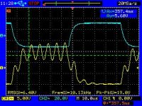
When this plot was make there was a lot of 60hz hum and harmonics, and what I believe is an oscillation up near 20KHz. The amp sounded better at 85ma than 60ma.
What would consider more optimal?
When this plot was make there was a lot of 60hz hum and harmonics, and what I believe is an oscillation up near 20KHz. The amp sounded better at 85ma than 60ma.
What would consider more optimal?
Attachments
Last edited:
I like the screen control better as it is more elegant (simple, concise). Both methods achieved the same result, although I will concede that cathode voltage control is more of a brute force technique.
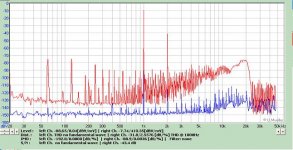
I'm using a GSXE15-8-3.5K transformer and had some issues with opt resulting in a constant oscillation around 130KHz.
A Zobel stabilized it but it is marginal as implemented. Increasing dampening results in greater roll off of high frequencies so it is a tradeoff.
There is a discontinuity at mid transition that looks like crossover distortion. However, this is a SE amp not a PP amp. This is where an oscillation initiates when no Zobel is present.
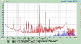
Frequency response is good, in part to use of a 15W transformer in an 8W amp.
10Hz -8.4dB
20hZ -2.5dB
100hZ +0.091dB
200hZ +0.27dB
1KHz 0dB
2KHz 0dB
10KHz -0.47dB
20KHz -2.05dB
30KHz -4.75dB
40KHz -7.5dB
Distortion is just starting at 20Hz at 1W out.
Sound is clean and crisp with good attack on percussion and good voice definition. I'm still only testing with one channel.
I'm using a GSXE15-8-3.5K transformer and had some issues with opt resulting in a constant oscillation around 130KHz.
A Zobel stabilized it but it is marginal as implemented. Increasing dampening results in greater roll off of high frequencies so it is a tradeoff.
There is a discontinuity at mid transition that looks like crossover distortion. However, this is a SE amp not a PP amp. This is where an oscillation initiates when no Zobel is present.
Frequency response is good, in part to use of a 15W transformer in an 8W amp.
10Hz -8.4dB
20hZ -2.5dB
100hZ +0.091dB
200hZ +0.27dB
1KHz 0dB
2KHz 0dB
10KHz -0.47dB
20KHz -2.05dB
30KHz -4.75dB
40KHz -7.5dB
Distortion is just starting at 20Hz at 1W out.
Sound is clean and crisp with good attack on percussion and good voice definition. I'm still only testing with one channel.
Attachments
Last edited:
Here is the data sheet I translated for the 6P41S. The graphs are too large to upload, however they can be found in the original djvu document at the radiolamp web site if you scroll down to 6P41S, click on it then the djvu at the top of the page. or email me and I'll send the entire pdf (2.3MB)
Ðàäèîëàìïû íà áóêâó (öèôðó) 6
Ðàäèîëàìïû íà áóêâó (öèôðó) 6
Attachments
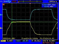
I ran into an interesting configuration tonight. Distortion is almost totally 2nd harmonic at 1W out and if I remove the 2nd harmonic from the FFT I only get .0028%thd.
Max output is near 6.8W before clipping.
Anyone care to guess how it is configured?
Max output is near 6.8W before clipping.
Anyone care to guess how it is configured?
Attachments
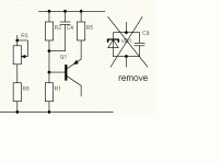
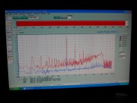
I've found that there is not one configuration (set of bias conditions) that result in minimization of upper harmonics, but rather it appears that there may be a curve on which this occurs. There may even be several curves or a multidimensional surface over which this occurs as I've found a large disparity in trying to plot a curve. I suspect I need to fix some variables (Va, Vg, Vs, Ik, etc) in order to minimize the variation.
It is not just that 3rd is minimized, but all the upper harmonics vary with adjustments while the second remains at virtually the same level.
Ignore C5, it was removed.
It is not just that 3rd is minimized, but all the upper harmonics vary with adjustments while the second remains at virtually the same level.
Ignore C5, it was removed.
Attachments
Last edited:
Looks like your quite original amp is asking for some better output tube. 😉
I would try EL34 there.
I would try EL34 there.
Last edited:
I switched to a regulated 250V supply and strapped the 6P41S in triode mode before trying the 7027A (I don't have any EL34s). I got less than 2%thd at 59mA Ik. If the second harmonic is excluded, distortion drops to less than 0.01%
The Mu-stage itself is putting out 0.33% distortion at 13Vrms drive to the 6P41S at 1W out. Minus second harmonic the remainder account for 0.05%thd from the MuStage.
I then tried the 7027A in triode mode at 250V B+ and got over 5%thd at 82mA as the best results. Again the odd harmonic distribution can be adjusted but not nearly as much as the 6P41S.
Finally I tried a 6P3S (not -E) and got 2.9%thd at 63mA. Excluding 2nd harmonic I could minimize remaining harmonics to less than 0.16%thd.
The first photo is a screen shot of the distortion with the 6P3S. Note that the 3rd, 5th and 7th harmonics are below the 2nd, 4th and 6th. This is what I find interesting. I can change the bias and they will track together while the 2nd harmonic does not change at all.
Attachments
Last edited:
- Status
- Not open for further replies.
- Home
- Amplifiers
- Tubes / Valves
- Closed loop stability help needed.