Hey, I just purchased a quite old Digidesign interface, and although it sounds quite alright I think it could use some help with a new clock design and some electrolytics and maybe opamps replacement.
I am thinking of two crystek clocks powered by a quality regulator.
I made some digging and I can't decide where in the existing clock should I intervene. Should I search for a Oscillator Frequency selector pin and send one clock signal where I should be or remove the old crystals and buffer inverters and go to their output for both the crysteks. Here an image of the existing clock:
Attachments
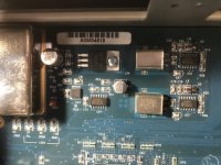
The 74HCU04 chips could be providing the gain needed to make an oscillator starting with the crystals. What voltage is that stuff running at? 3.3v? 5v?
Regarding Crystek clocks, getting the best out of them can be a bit tricky. Using Chinese power supply modules to power them is probably not the best way to go. There are too many junky passive parts on such modules even if the regulator chip is real. Also, the voltage regulator should be on the same ground plane as the clocks, not connected with wires to clock ground.
EDIT: Early Digidesign interfaces had a reputation for sounding bad at least among some recording engineers. Probably lots of things would need fixing or modding to bring them up to the level of a modern Focusrite Scarlett type interface (which IMHO is good, but not great).
Last edited:
I just got a little deeper to it, with an oscilloscope, and analyse it. The clock output is at 3.3v (the regulator there is outputing 5v) and it has a peculiar system for the oscillator sellection. it drops the Vcc of the 74HCU04 while is not the oscillator selected, but the two oscillators output are going in two separate inputs of the FPGA. I was planning designing a new mini board for the crysteks and their regulator in common ground plane, getting as input an unregullated Voltage and tapping the oscillator selection line and built my own selection line on the board with a gate. I have seen designs that use inverters after the crysteks and I was wandering if this is for buffering, and maybe it is useful to use the 74HCU04, or remove them, and solder my output lines on the output pad of the removed 74HCU04s.
The PSU of the 192 IO is SMPS but definitely not a cheap Chinese one. Like maybe older and cheaper designs as 002 and 003. It occupies one third of the chassis, it is very well shielded, and seems like a specific design for the interface having multiple individual outputs and some quality caps. I don't think it is the weak point of this design.
I am also considering changing the AD8510 to a little faster OPA1611 of the analog output stage
If clock buffering is needed, NB3L553 is something I would use in preference to some kind of 74xxx04.
Regarding Crystek 957 clocks, despite the tri-state output enable/disable pin on them they sound better to me if both clocks are left fully running at all times. IME, it takes them about 3-days of running to reach the lowest audible jitter level (same thing, again IME, for Accusilicon clocks). NB3L5530 has an output enable that could be used to gate the clock outputs, assuming each clock has its own buffer chip. I have seen that used in a good quality commercial dac design.
Regarding Crystek 957 clocks, despite the tri-state output enable/disable pin on them they sound better to me if both clocks are left fully running at all times. IME, it takes them about 3-days of running to reach the lowest audible jitter level (same thing, again IME, for Accusilicon clocks). NB3L5530 has an output enable that could be used to gate the clock outputs, assuming each clock has its own buffer chip. I have seen that used in a good quality commercial dac design.
Last edited: