I know that there a few of these around, but I thought I'd share this. Combines the features of Rod Elliott's design here: Project 23 and Mark Hennessy's design here: Active Speaker
Mine triggers lower than the other two at 5V below the rails, but even on my small amp running from +/- 12V, that is only 2dB before the supply rails and 1.5dB below maximum output. To change this, simply change the zeners from 4v7 to whatever you prefer.
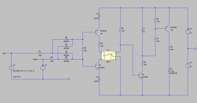
The transistors shown should be good for +/-20V, BC639 and BC640 can be used if you want to go higher though you will also need to change R4 and probably D3 to D6 if you go too high. You can just swap Q1 and Q2 etc. and run everything right of the opto on 12V.
C1 and R7 make the LED stay on for 30ms longer than the clipping to make it easier to see short duration clipping.
A few values (e.g. R1 and R2) were changed from the original design to suit what I had lying around (must buy some 1k resistors), so experiment and enjoy.
Brian
Mine triggers lower than the other two at 5V below the rails, but even on my small amp running from +/- 12V, that is only 2dB before the supply rails and 1.5dB below maximum output. To change this, simply change the zeners from 4v7 to whatever you prefer.
The transistors shown should be good for +/-20V, BC639 and BC640 can be used if you want to go higher though you will also need to change R4 and probably D3 to D6 if you go too high. You can just swap Q1 and Q2 etc. and run everything right of the opto on 12V.
C1 and R7 make the LED stay on for 30ms longer than the clipping to make it easier to see short duration clipping.
A few values (e.g. R1 and R2) were changed from the original design to suit what I had lying around (must buy some 1k resistors), so experiment and enjoy.
Brian
Attachments
Is there a "worst case" set of inputs that gives a false positive output?
For example: the left channel and right channel are both playing 1 kHz sinewaves whose amplitudes are 5V. With 12V supplies the output is 7V away from the rails and that's not "clipping". However, the two 1 kHz sinewaves are exactly 180 degrees out of phase. When the Left channel is at a peak (+5V) the Right channel is at a trough (-5V), and vice versa. So the input to the bridge rectifier D3-D6 is 10 volts. Is that large enough to make the clipping indicator LED come on, incorrectly?
For example: the left channel and right channel are both playing 1 kHz sinewaves whose amplitudes are 5V. With 12V supplies the output is 7V away from the rails and that's not "clipping". However, the two 1 kHz sinewaves are exactly 180 degrees out of phase. When the Left channel is at a peak (+5V) the Right channel is at a trough (-5V), and vice versa. So the input to the bridge rectifier D3-D6 is 10 volts. Is that large enough to make the clipping indicator LED come on, incorrectly?
Is there a "worst case" set of inputs that gives a false positive output?
For example: the left channel and right channel are both playing 1 kHz sinewaves whose amplitudes are 5V. With 12V supplies the output is 7V away from the rails and that's not "clipping". However, the two 1 kHz sinewaves are exactly 180 degrees out of phase. When the Left channel is at a peak (+5V) the Right channel is at a trough (-5V), and vice versa. So the input to the bridge rectifier D3-D6 is 10 volts. Is that large enough to make the clipping indicator LED come on, incorrectly?
I had to check, but no it doesn't.
Q1 compares the highest peak of left OR highest peak of right with the voltage on its emitter. This combined signal has to be high enough to turn Q1 off and 5 volts isn't enough. Q2 does the same comparison with the negative part of the cycles.
The attached sim is what you suggested.
Thanks for making me think about it a bit more though.
Brian
Attachments
- Status
- Not open for further replies.